
La ringraziamo per aver scelto un prodotto Ariston, sicuro e davvero facile da usare. Per conoscerlo, utilizzarlo al
meglio e a lungo, le consigliamo di leggere questo manuale. Grazie
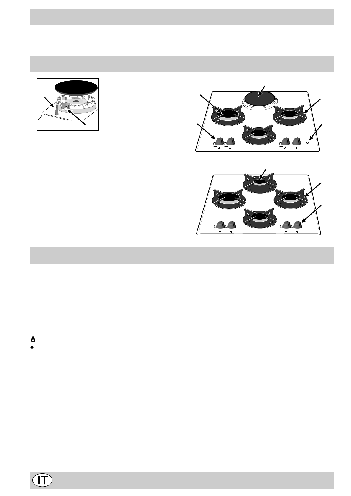
Visto da vicino
G
F
A
B
D
A. Bruciatori gas
B. Griglie di appoggio per recipienti di cottura
C. Manopole di comando dei bruciatori gas o della
piastra elettrica
D. Candela di accensione dei bruciatori gas (presen-
te solo su alcuni modelli)
F. Dispositivo di sicurezza (presente solo su alcuni mo-
delli) — Interviene in caso di spegnimento accidentale
della fiamma (trabocco di liquidi, correnti d’aria, …)
bloccando l’erogazione del gas al bruciatore.
G. Piastra elettrica (presente solo su alcuni modelli)
H. Spia di funzionamento piastra elettrica (presente
solo su alcuni modelli)
Come utilizzarlo
Su ciascuna manopola è indicata la posizione del bruciatore gas corrispondente.
Bruciatori gas
Sono di diverse dimensioni e potenze. Scegliete quello
più adatto al diametro del recipiente da utilizzare.
Il bruciatore prescelto può essere regolato dalla manopola corrispondente come segue:
• Spento
Massimo
Minimo
Per accendere uno dei bruciatori, avvicinare allo stesso una fiamma o un accenditore, premere a fondo e
ruotare la manopola corrispondente in senso antiorario
fino alla posizione di massima potenza.
Nei modelli dotati di dispositivo di sicurezza «F«, è necessario mantenere premuta la manopola per circa 6 secondi finchè non si scalda il dispositivo che mantiene automaticamente accesa la fiamma .
Nei modelli dotati di candela di accensione «D«, per
accendere il bruciatore prescelto è sufficiente prima premere a fondo la manopola corrispondente, poi ruotarla in
senso antiorario fino alla posizione di massima potenza,
tenendola premuta fino alla avven uta accensione.
C
1
6
2
5
4
3
H
Avvertenza: nel caso di una estinzione accidentale delle
fiamme del bruciatore, chiudere la manopola di comando
e ritentare l’accensione dopo almeno 1 minuto.
Per spegnere il bruciatore occorre ruotare la manopola
in senso orario fino all’arresto (corrispondente al simbolo
“•”).
Piastra elettrica (presenti solo su alcuni modelli)
Possono essere: «normali» o «rapide», quest’ ultime si riconoscono dalle altre per la presenza di un bollo rosso al centro.
La regolazione può essere effettuata ruotando la manopola
corrispondente in senso orario o anti-orario su 6 posizioni
diverse:
0 Spento
1 Potenza minima
2÷5 Potenz e intermedie
6 Potenza massima
Nel capitolo «Consigli pratici per l’uso» sono riportate le corrispondenze fra le posizioni indicate sulle manopole e l’uso
per il quale le piastre sono consigliate.
Per qualsiasi posizione della manopola div ersa da quella di
spento, si ha l’accensione della spia di funzionamento «H«.
2
Come tenerlo in forma
Prima di ogni operazione disconnettere l’apparecchio dall’
alimentazione elettrica.
Per una lunga durata del piano è indispensabile eseguire frequentemente una accurata pulizia generale,
tenendo presente che:
· per la pulizia non utilizzare apparecchi a vapore
• le parti smaltate ed in vetro vanno lavate con acqua
tiepida senza usare polveri abrasive e sostanze corrosive che potrebbero rovinarli;
• gli elementi mobili dei bruciatori vanno lavati frequentemente con acqua calda e detersivo avendo cura di
eliminare le eventuali incrostazioni;
• nei piani dotati di accensione automatica occorre procedere frequentemente ad una accurata pulizia della
parte ter minale dei dispositivi di accensione istantanea elettronica e verificare che i fori di uscita del gas
non siano ostruiti;
• il piano va pulito con prodotti per la pulizia dei vetri.
Evitare l’utilizzo di prodotti e pagliette abrasive che possono provocare rigature sul vetro.
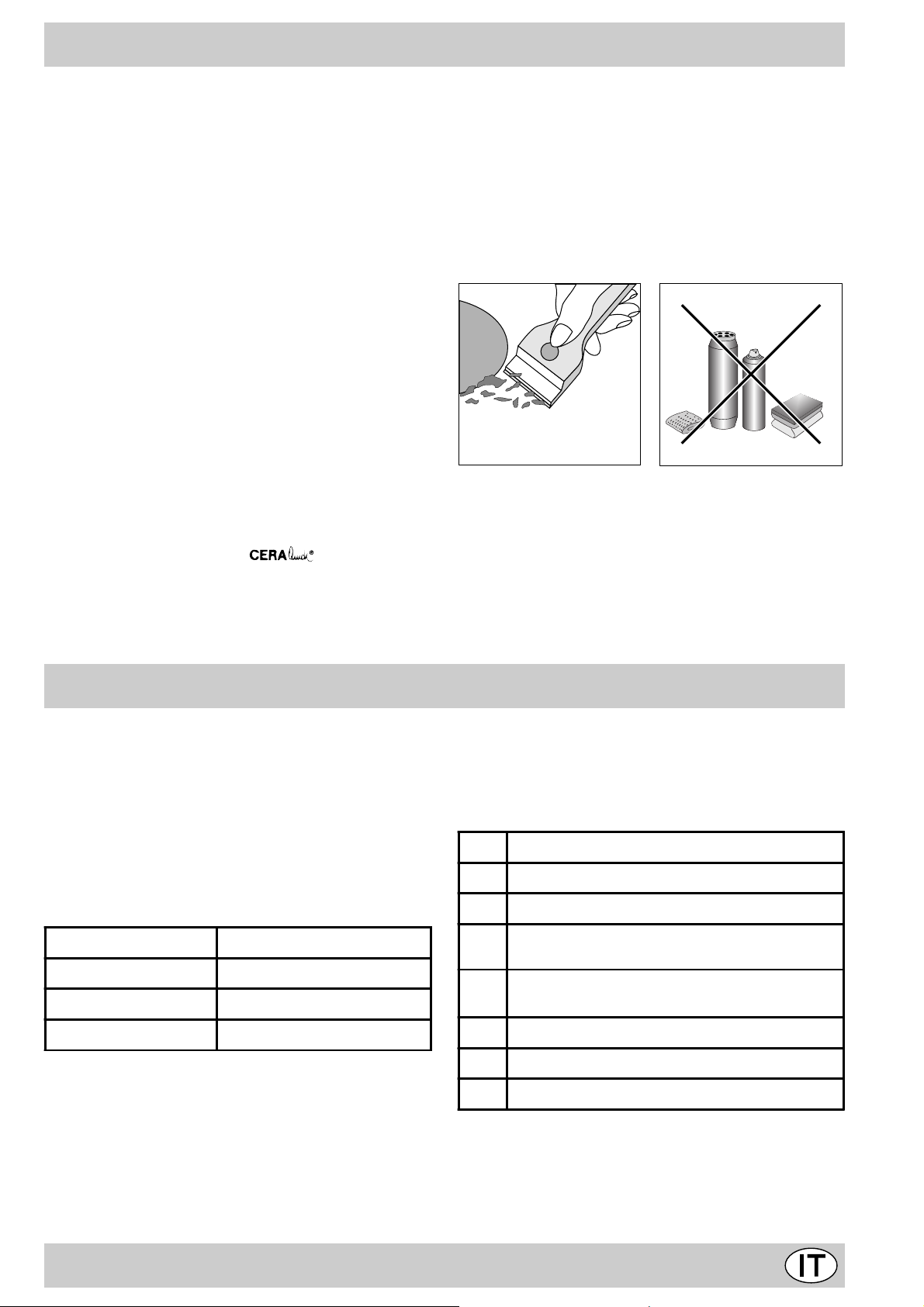
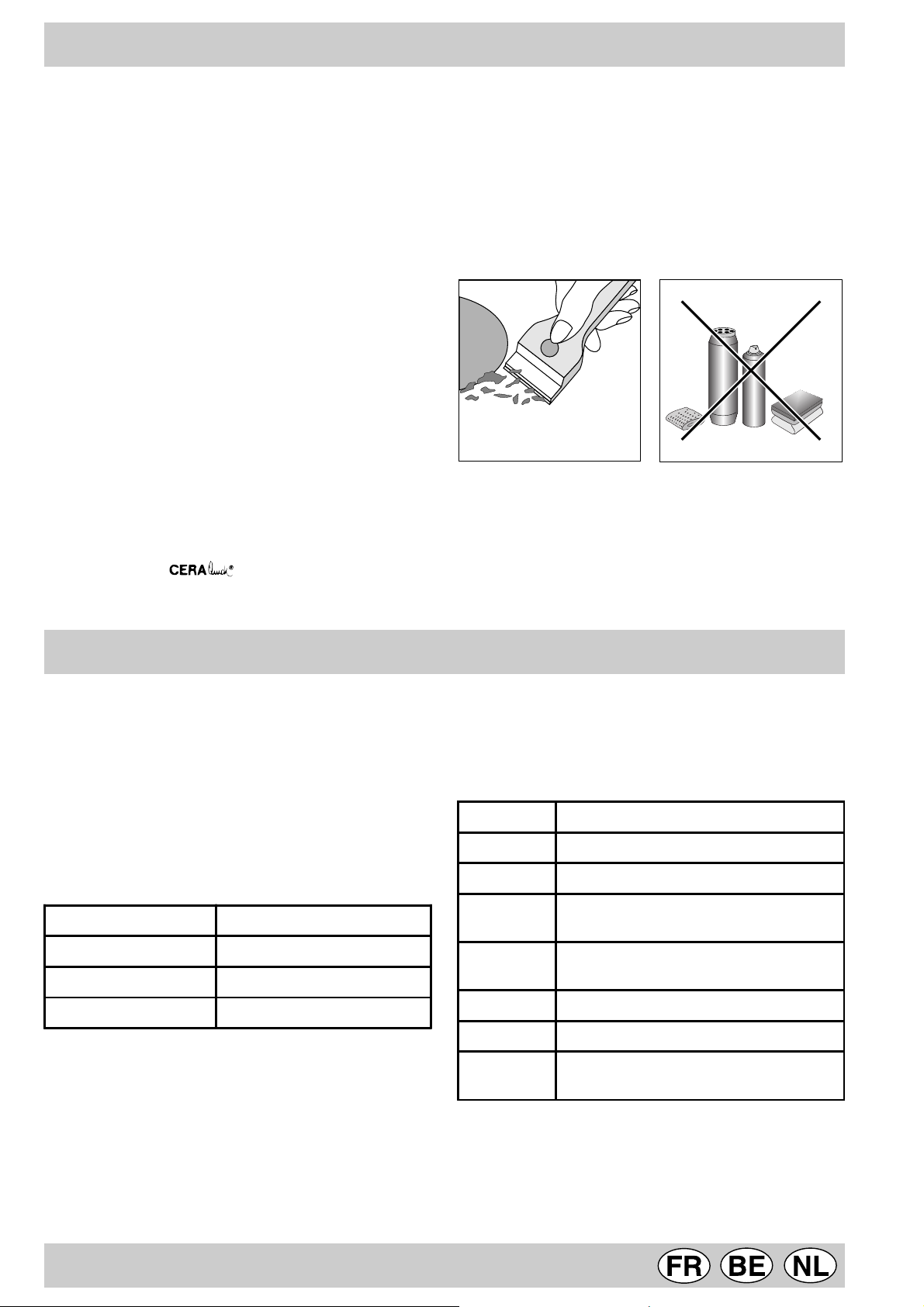
• la superficie del piano dovrà essere pulita regolarmente
con una soluzione di acqua tiepida e detergente non
abrasivo. Dapprima togliere dal piano di cottura tutti i
resti di vivande e spruzzi di grasso con un raschietto
per la pulizia per esempio (non in dotazione) (Fig. A).
Pulire il piano di cottura quando è tiepido; utilizzare un
prodotto di pulizia adatto, strofinare con un panno
umido ed asciugare. Zucchero o vivande ad alto contenuto zuccherino vanno eliminati immediatamente
dalla zona di cottura ancora calda con un raschietto.
In nessun caso utilizzare spugne o prodotti abrasivi,
anche detersivi chimicamente aggressivi come gli
spray da f orno o prodotti smacchianti vanno evitati (Fig.
B);
Fig. A Fig. B
Ingrassaggio dei rubinetti
Con il tempo può verificarsi il caso di un rubinetto che si
blocchi o presenti difficoltà nella rotazione, pertanto sarà
necessario provvedere alla sostituzione del rubinetto stesso.
N.B.: Questa operazione de ve essere effettuata da un
tecnico autorizzato dal costruttore.
Consigli d’uso
Consigli pratici per l’uso dei bruciatori
Al fine di ottenere il massimo rendimento è utile ricordare
quanto segue:
• utilizzare recipienti adeguati a ciascun bruciatore (vedere tabella) al fine di evitare che le fiamme fuoriescano
dal fondo dei recipienti.
• utilizzare sempre recipienti a fondo piatto e con coperchio.
• al momento dell’ebollizione ruotare la manopola fino
alla posizione di minimo.
Bruciatore ø Diametro recipienti (cm)
Rapido (R) 24 – 26
Semi Rapido (S) 16 – 20
Ausiliario (A) 10 – 14
Per identificare il tipo di bruciatore f ate riferimento ai disegni presenti nel paragrafo «Caratteristiche dei bruciatori
ed ugelli»
Consigli pratici per l’uso delle piastre elettriche
Per e vitare dispersioni di calore e danni alla piastra è bene
usare recipienti con fondo piano e di diametro non inferiore a quello della piastra.
Pos. Piastra normale o rapida
Spento
0
Cottura di verdure, pesci
1
Cottura di patate (a vapore) minestre, ceci,
2
fagioli
Proseguimento di cottura di grandi quantità di
3
cibi, minestroni
4 Arrostire (medio)
Arrostire (forte)
5
Rosolare o raggiungere bollitura in poco tempo
6
Prima di utilizzarle per la prima volta, è necessario
riscaldare le piastre di cottura alla massima temperatura per circa 4 minuti, senza pentola. Durante questa
fase iniziale, il rivestimento protettivo si indurisce e
raggiunge la massima resistenza.
3

C’è qualche problema?
Può accadere che il piano non funzioni o non funzioni
bene. Prima di chiamare l’assistenza, vediamo che cosa
si può fare.
Innanzi tutto verificare che non ci siano interruzioni nelle
reti di alimentazione gas ed elettrica, ed in particolare i
rubinetti gas a monte del piano siano aperti.
Il bruciatore non si accende o la fiamma non è
uniforme.
Av ete controllato se:
• Sono ostruiti i fori di uscita del gas del bruciatore.
• Sono montate correttamente tutte le parti mobili che
compongono il bruciatore.
• Ci sono correnti d’aria nelle vicinanze del piano.
La fiamma non rimane accesa nelle versioni con
sicurezza.
Av ete controllato se:
• Non avete premuto a f ondo la manopola.
• Non avete mantenuto premuta a fondo la manopola
per un tempo sufficiente ad attivare il dispositivo di
sicurezza.
• Sono ostruiti i fori di fuoriuscita del gas in corrispondenza del dispositivo di sicurezza.
Il bruciatore in posizione di minimo non rimane
acceso.
Av ete controllato se:
• Sono ostruiti i fori di fuoriuscita del gas.
• Ci sono correnti d’aria nelle vicinanze del piano.
• La regolazione del minimo non è corretta (Vedi paragrafo «Regolazione minimi»).
I recipienti sono instabili.
Av ete controllato se:
• Il fondo del recipiente è perfettamente piano .
• Il recipiente è centrato sul bruciatore.
• Le griglie sono state invertite.
Se, nonostante tutti i controlli, il piano non funziona e l’inconveniente da voi rilevato persiste, chiamate il Centro
Assistenza Tecnica Merloni Elettrodomestici più vicino, comunicando queste informazioni:
— Il tipo di guasto.
— La sigla del modello (Mod. …) riportata sul certificato di
garanzia.
Non ricorrete mai a tecnici non autorizzati e rifiutate sempre l’installazione di pezzi di ricambio non originali.
La sicurezza una buona abitudine
Per garantire l’efficienza e la sicurezza di questo elettr odomestico:
• rivolgetevi esclusivamente a centri di assistenza tecnica autorizzati
• richiedete sempre l’utilizzo di parti di ricambio originali
• Questo libretto riguarda un piano di cottura da incasso
di classe3.
• L’apparecchio è concepito per uso non professionale
nelle abitazioni e le sue caratteristiche non vanno modificate.
• Le istruzioni sono valide solo per i paesi di destinazione i cui simboli figurano sul libretto e sulla targa matricola.
• La sicurezza elettrica di questo apparecchio è assicurata soltanto quando lo stesso è correttamente collegato ad un efficiente impianto di messa a terra come
previsto dalle vigenti norme di sicurezza.
T rattandosi di fonti di pericolo, evitare c he bambini e
incapaci abbiano contatti con:
— i comandi e l’apparecchio in genere;
— gli imballaggi (sacchetti, polistirolo, chiodi ecc.);
— l’apparecchio, durante e subito dopo il funzionamento,
visto il surriscaldamento;
— l’apparecchio inutilizzato (in questo caso vanno rese
innocue le parti che potrebbero essere pericolose).
— che il cavo di alimentazione di piccoli elettrodomestici
finisca su parti calde dell’apparecchio;
— l’esposizione ad agenti atmosferici (pioggia, sole);
— l’utilizzo di liquidi infiammabili nei pressi;
— l’impiego di adattatori, prese multiple e/o prolunghe;
— l’impiego di pentole instabili o deformate;
— Il piano è resistente agli sbalzi di temperatura e
agli urti. Tuttavia se colpito con oggetti come
taglierini o utensili con bordi appuntiti può rompersi. In questo caso togliete subito l’alimentazione e rivolgetevi ad un centro di assistenza autorizzato.
— tentativi di installazione o riparazione senza l’intervento di personale qualificato.
Occorre assolutamente rivolgersi a personale
qualificato nei seguenti casi:
— installazione (secondo le istruzioni del costruttore);
— quando si hanno dubbi sul funzionamento;
— sostituzione della presa in caso di incompatibilità con
la spina dell’apparecchio.
V anno evitate le seguenti operazioni:
— toccare l’apparecchio con parti del corpo umide;
— l’uso quando si è a piedi nudi;
— tirare l’apparecchio o il cavo di alimentazione per staccarli dalla presa di corrente;
— operazioni improprie e pericolose;
— ostruire le aperture di ventilazione o smaltimento calore;
Occorre rivolgersi a centri di assistenza autorizzati
dal costruttore nei seguenti casi:
— in caso di dubbio sull’integrità dell’apparecchio dopo
aver tolto l’imballaggio;
— danneggiamento o sostituzione del cavo di alimentazione;
— in caso di guasto o cattivo funzionamento, richiedendo i ricambi originali.
4
È opportuno effettuare le seguenti operazioni:
— solo la cottura dei cibi evitando altre operazioni;
— verificare l’integrità dopo aver tolto l’imballaggio;
— disconnettere l’apparecchio dalla rete di alimentazione elettrica in caso di cattivo funzionamento e prima di
qualsiasi operazione di pulizia o manutenzione;
— quando inutilizzato, disinserire l’apparecchio dalla rete
elettrica e chiudere il rubinetto del gas (se previsto);
Installazione dei piani da incasso
— controllare sempre che le manopole siano nella posizione “•”/”o” quando l’apparecchio non è utilizzato;
— tagliare il cavo di alimentazione dopo averlo
disconnesso dalla rete elettrica quando si decide di
non utilizzare più l’apparecchio.
• Il costruttore non può essere considerato responsabile per eventuali danni derivanti da: errata installazione, usi impropri, erronei ed irragionev oli.
Le istruzioni che seguono sono rivolte all’installatore qualificato affinchè compia le operazioni di installazione
regolazione e manutenzione tecnica nel modo più corretto e secondo le norme in vigore.
Importante: qualsiasi intervento di regolazione, manutenzione etc. de ve essere eseguito con il piano elettricamente disinserito.
Posizionamento
Importante: questo apparecchio può essere installato e
funzionare solo in locali permanentemente ventilati secondo le prescrizioni delle Norme UNI-CIG 7129 e 7131
in vigore. Deb bono essere osservati i seguenti requisiti:
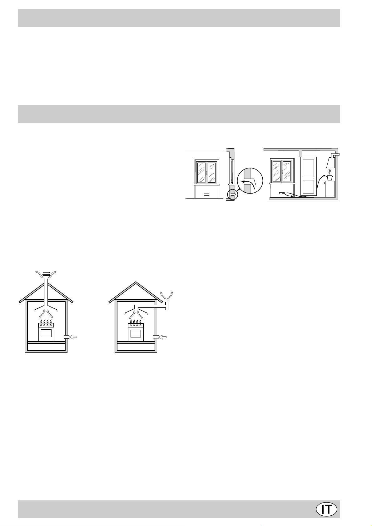
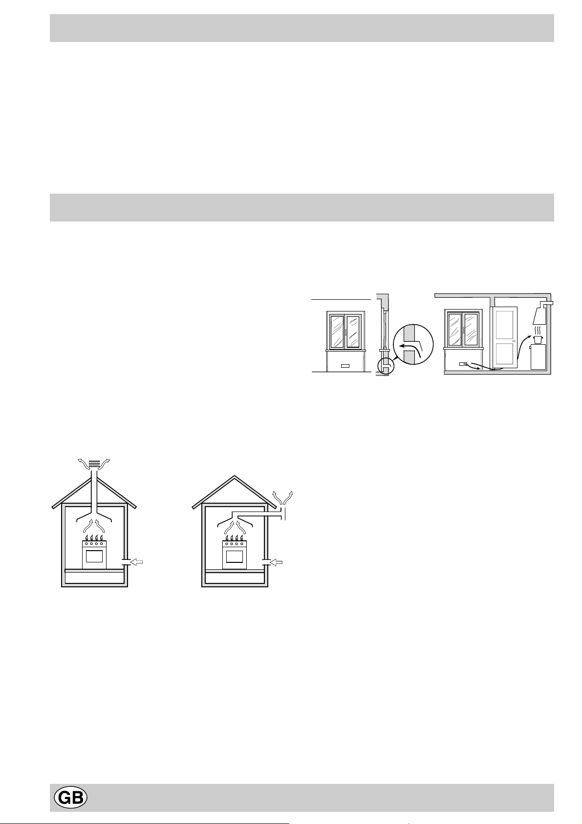
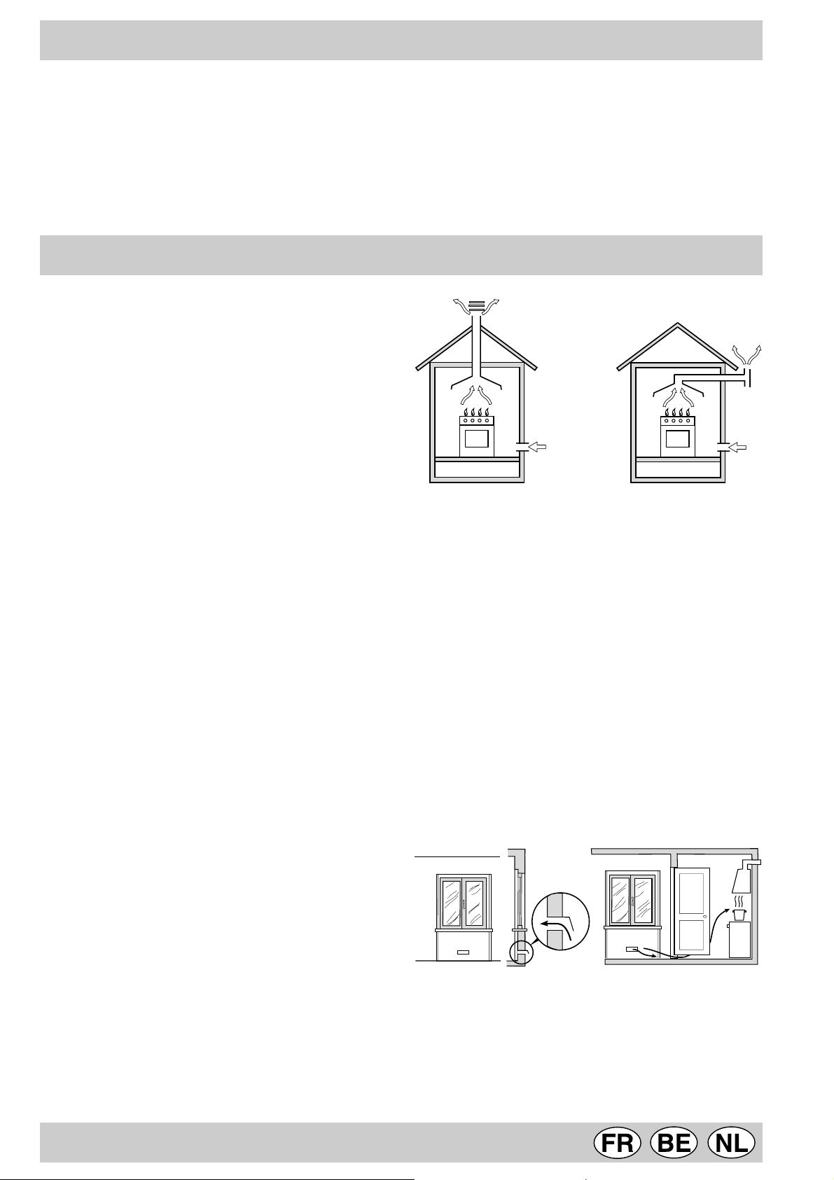
a) Il locale deve prevedere un sistema di scarico all’ester-
no dei fumi della combustione, realizzato tramite una
cappa o tramite un elettroventilatore che entri automaticamente in funzione ogni volta che si accende l’apparecchio.
Particolare A Locale Locale da
adiacente ventilare
A
Esempi di aperture di ventilazione Maggiorazione della fessura fr a
per l’aria comburente porta e pavimento
Fig. A Fig. B
c) Un utilizzo intensivo e prolungato dell’apparecchio può
necessitare di una aerazione supplementare per esempio l’apertura di una finestra o una aerazione più efficace aumentando la potenza di spirazione meccanica
se essa esiste.
d) I gas di petrolio liquefatti, più pesanti dell’aria, rista-
gnano verso il basso. Quindi i locali contenenti bidoni
di GPL debbono prevedere delle aperture verso l’esterno così da permettere l’evacuazione dal basso delle
eventuali fughe di gas . P ertanto i bidoni di GPL, siano
essi vuoti o parzialmente pieni, non debbono essere
installati o depositati in locali o vani a livello più basso
del suolo (cantinati, ecc.). É opportuno tenere nel locale solo il bidone in utilizzo, collocato in modo da non
essere soggetto all’azione diretta di sorgenti di calore
(forni, camini, stufe, ecc.) capaci di portarlo a temperature superiori ai 50°C.
In camino o in canna fumaria ramificata Direttamente all’esterno
(riservata agli apparecchi di cottura)
b) Il locale dev e pre vedere un sistema che consenta l’af-
flusso dell’aria necessaria alla regolare combustione.
La portata di aria necessaria alla combustione non deve
essere inferiore a 2 m³/h per kW di potenza installata.
Il sistema può essere realizzato prelevando direttamente l’aria dall’esterno dell’edificio tramite un condotto di
almeno 100 cm² di sezione utile e tale che non possa
essere accidentalmente ostruito. Per gli apparecchi privi sul piano di lavoro, del dispositivo di sicurezza per
assenza di fiamma, le aperture di ventilazione debbono essere maggiorate nella misura del 100%, con un
minimo di 200cm² (Fig. A). Ovvero , in maniera indiretta da locali adiacenti, dotati di un condotto di ventilazione con l’esterno come sopra descritto, e che non
siano parti comuni dell’immobile, o ambienti con pericolo di incendio, o camere da letto (Fig. B).
Installazione dei piani da incasso
E’ possibile l’installazione a fianco di mobili la cui altezza
non superi quella del piano di lavoro . La parete a contatto
con la parete posteriore della cucina deve essere in materiale ininfiammabile. Durante il funzionamento la parete posteriore della cucina può raggiungere una temperatura di 50°C superiore a quella ambiente. P er una corretta
installazione della cucina vanno osservate le seguenti
precauzioni:
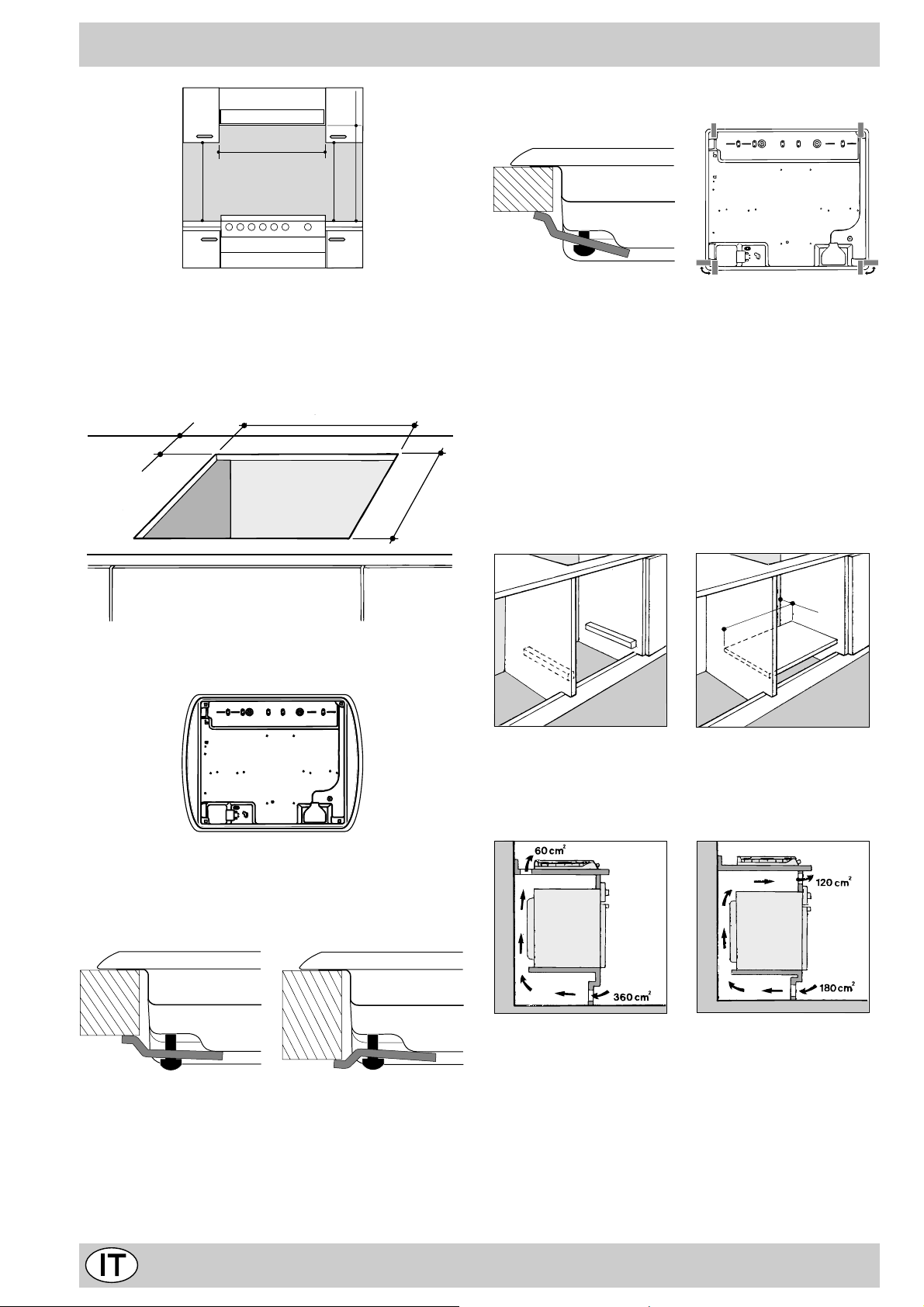
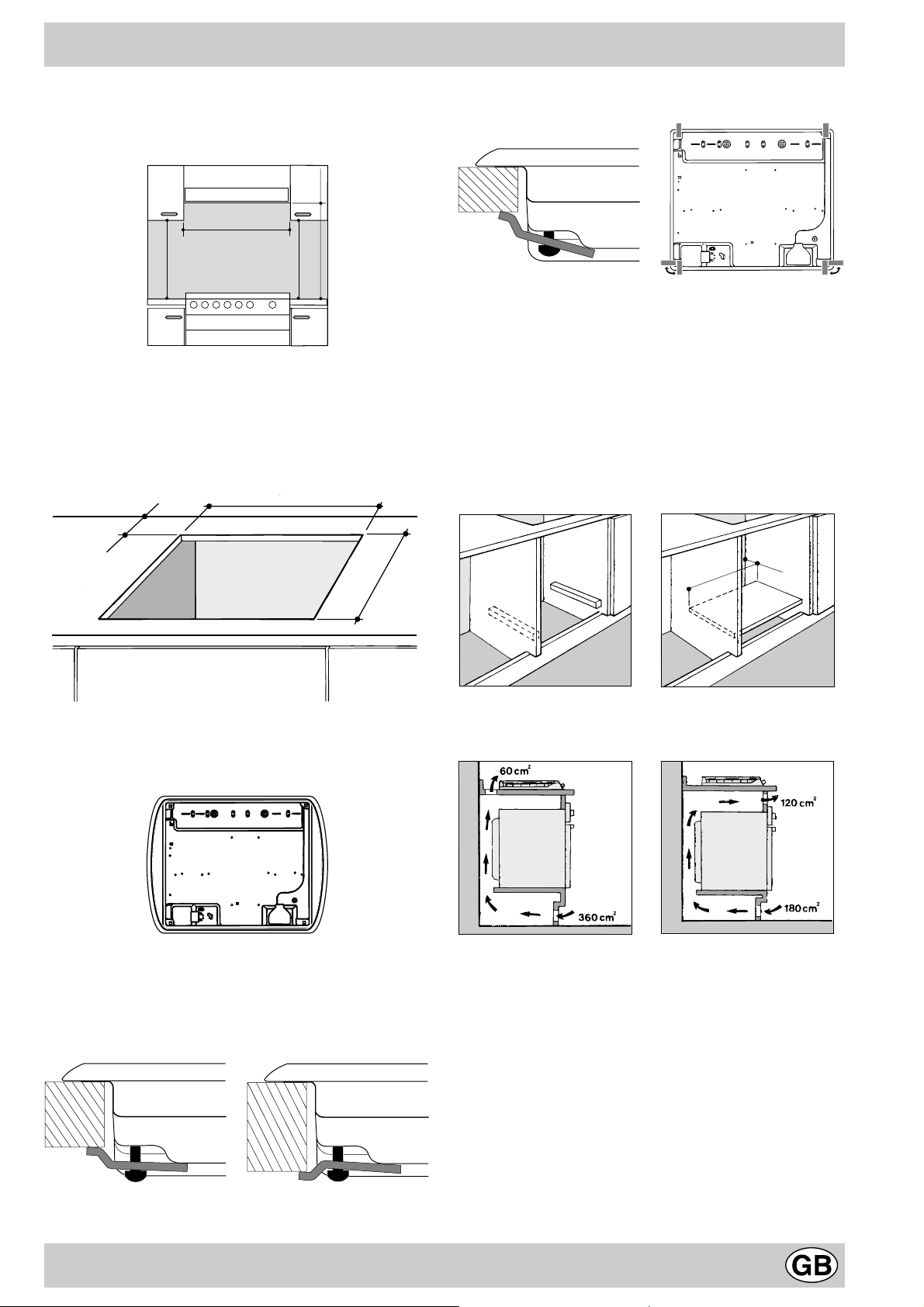
a) I mobili situati a fianco, la cui altezza superi quella del
piano di lavoro , debbono essere situati ad almeno 600
mm. dal bordo del piano stesso.
b) Le cappe debbono essere installate secondo i requisi-
ti richiesti nei libretti istruzioni delle cappe stesse, comunque ad una distanza minima di 650 mm.
c) Posizionare i pensili adiacenti alla cappa ad un’altezza
minima dal top di 420 mm (Fig. C).
5
HOOD
Min. mm.
600
mm.
420
Min.
mm. with hood
420
650
Min. mm.
min.
mm. without hood
700
min.
Fig. C
d) Allorchè il piano di cottura venga installato sotto un
pensile, quest’ultimo dovrà mantenere una distanza
minima dal top pari a 700 mm (millimetri) come da Fig.
C.
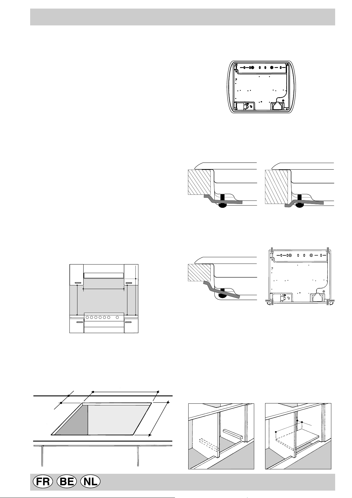
e) Il vano del mobile dovrà avere le dimensioni indicate
nella figura.
555 mm.
55 mm.
475 mm.
Av anti
Posizione gancio per Dietro
top H=20mm
N.B: Usare i ganci contenuti nella «confezione accessori»
f) Nel caso in cui il piano non sia installato su di un forno
incasso, è necessario inserire un pannello di legno
come isolamento. Esso dovrà essere posizionato ad
una distanza minima di 20 mm. dalla parte inferiore
del piano stesso.
Nota: Nel caso in cui il piano sia installato su di un forno
incasso, è preferibile installare il forno in modo che appoggi su due listelli in legno; nel caso in cui sia presente
un piano continuo di appoggio questo deve a vere un’apertura posteriore di almeno 45 x 560 mm.
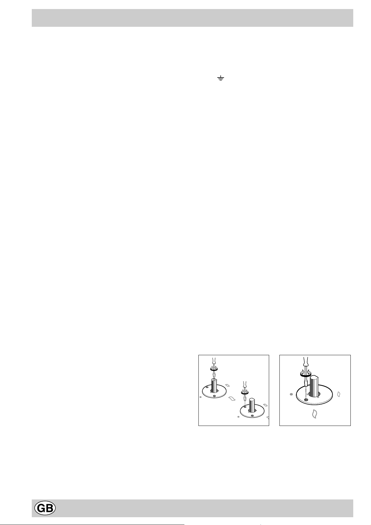
Prima di procedere al fissaggio al top, posizionare la
guarnizione (in dotazione) lungo il perimetro del piano
come rappresentato in figura.
Sono previsti dei ganci di fissaggio che consentono di
fissare il piano su top da 20 a 40 mm. di spessore . P er
un buon fissaggio del piano è consigliabile usare tutti i
ganci a disposizione.
Schema di fissaggio dei ganci
Posizione gancio per Posizione gancio per
top H=30mm top H=40mm
45 mm.
560 mm.
Nel caso di installazione sopra un forno da incasso senza
ventilazione forzata di raffreddamento, per consentire
un’adeguata areazione all’interno del mobile vanno garantite delle prese d’aria di ingresso e di uscita. Possibili
esempi di montaggio sono illustrati nelle figure sottostanti.
Collegamento gas
Il collegamento dell’apparecchio alla tubazione o alla bombola del gas dovrà essere effettuato come prescritto dalle
Norme UNI-CIG 7129 e 7131, solo dopo essersi accertati
che esso è regolato per il tipo di gas con cui sarà alimentato.
In caso contrario eseguire le operazioni indicate al paragrafo “Adattamento ai div ersi tipi di gas”. Nel caso di alimentazione con gas liquido, da bombola, utilizzare regolatori di
pressione conformi alle Norme UNI-CIG 7432.
Importante: per un sicuro funzionamento, per un adeguato
6
uso dell’energia e maggiore durata dell’apparecchiatura, assicurarsi che la pressione di alimentazione rispetti i valori
indicati nella tabella 1 “Caratteristiche dei bruciatori ed ugelli”.
Allaccio con tubo rigido (rame o acciaio)
L’allaccio all’impianto gas deve essere eff ettuato in modo da
non provocare sollecitazioni di alcun genere all’apparecchio .
Sulla rampa di alimentazione dell’apparecchio è presente
un raccordo a “L” orientabile, la cui tenuta è assicurata da
una guarnizione. Nel caso risulti necessario ruotare il raccordo sostituire tassativamente la guarnizione di tenuta (in
dotazione con l’apparecchio). Il raccordo di entr ata del gas
all’apparecchio è filettato 1/2 gas maschio cilindrico.
Allaccio con tubo flessibile in acciaio inossidabile a
parete continua con attacchi filettati
Il raccordo di entrata del gas all’apparecchio è filettato 1/
2 gas maschio cilindrico. Utilizzare esclusivamente tubi
conformi alla Norma UNI-CIG 9891 e guarnizioni di tenuta conformi alla UNI-CIG 9264. La messa in opera di tali
tubi deve essere effettuata in modo che la loro lunghezza, in condizioni di massima estensione, non sia maggiore di 2000 mm. Ad allacciamento avvenuto assicur arsi che
il tubo metallico flessibile non venga a contatto con parti
mobili o schiacciato.
Controllo tenuta
Ad installazione ultimata controllare la perfetta tenuta di
tutti i raccordi utilizzando una soluzione saponosa e mai
una fiamma.
Collegamento elettrico
I piani dotati di cavo di alimentazione tripolare, sono predisposti per il funzionamento con corrente alternata alla
tensione e frequenza di alimentazione indicate sulla
targhetta caratteristiche (posta sulla parte inferiore del
piano). Il conduttore di terra del ca vo è contraddistinto dai
colori giallo-verde. Nel caso di installazione sopr a un f orno da incasso l’allaccio elettrico del piano e quello del
forno deve essere realizzato separatamente, sia per ragioni di sicurezza elettrica che per facilitare l’eventuale
estraibilità del forno.
N.B: non utilizzare riduzioni, adattatori o derivatori in quanto essi potrebbero provocare riscaldamenti o bruciature.
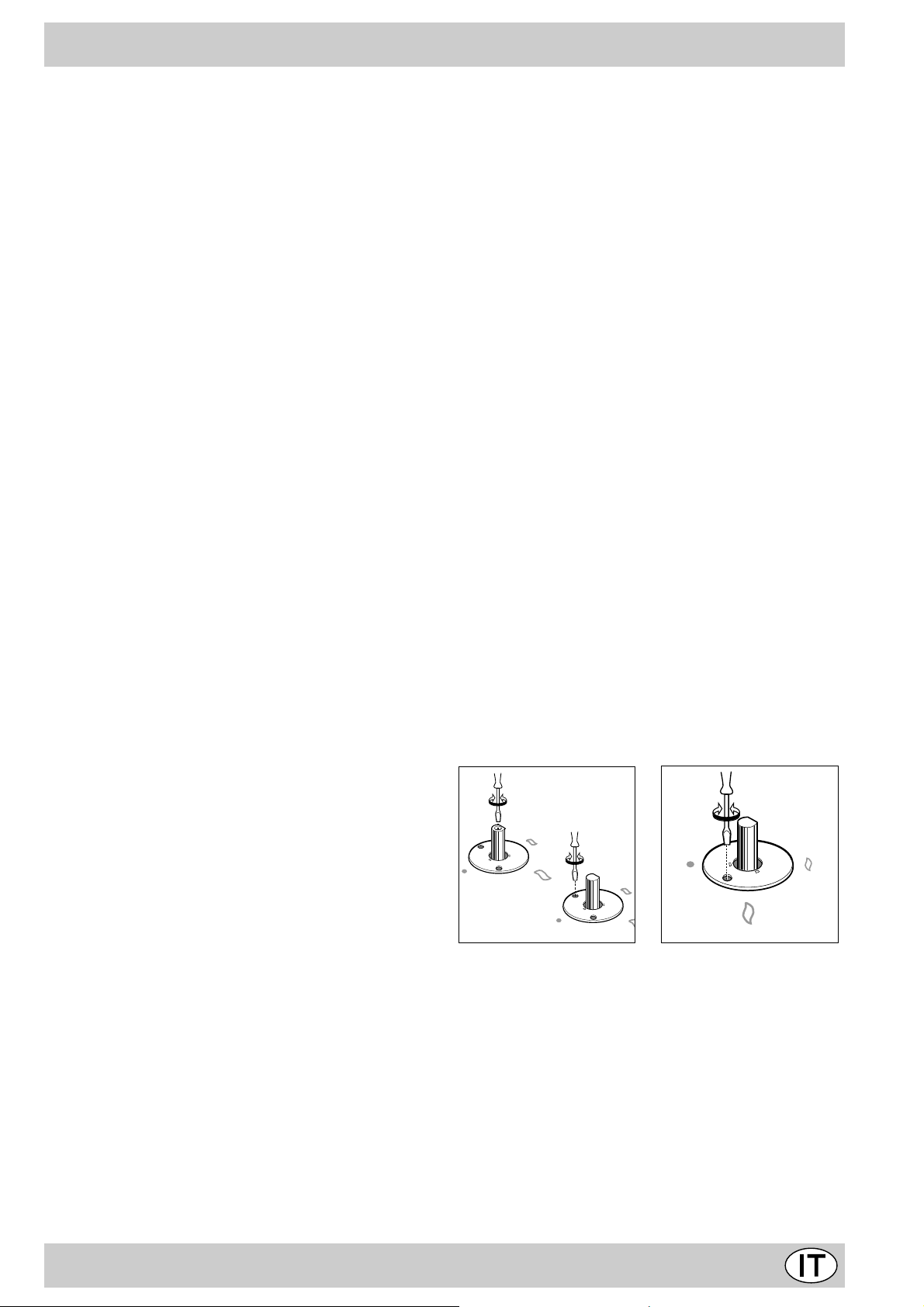
Adattamento ai diversi tipi di gas
Per adattare il piano ad un tipo di gas diverso da quello
per il quale esso è predisposto (indicato sulla etichetta
fissata nella parte inferiore del piano o sull’imballo), occorre sostituire gli ugelli dei bruciatori effettuando le seguenti operazioni:
• togliere le griglie del piano e sfilare i bruciatori dalle
loro sedi.
• svitare gli ugelli, servendosi di una chiave a tubo da
7mm. e sostituirli con quelli adatti al nuo v o tipo di gas
(vedi tabella 1 “Caratteristiche dei bruciatori ed ugelli”).
• rimontare le parti eseguendo all’inverso le oper azioni.
• al termine dell’operazione, sostituite la vecchia etichetta
taratura con quella corrispondente al nuovo gas d’utilizzo, reperibile presso i Nostri Centri Assistenza Tecnica.
Qualora la pressione del gas utilizzato sia diversa (o variabile) da quella prevista, è necessario installare, sulla
tubazione di ingresso, un appropriato regolatore di pressione, secondo UNI-CIG 7430 (regolatori per gas
canalizzati).
Regolazione aria primaria dei bruciatori
I bruciatori non necessitano di nessuna regolazione dell’aria primaria.
Regolazione minimi
Regolazione minimi.
• portare il rubinetto sulla posizione di minimo;
• togliere la manopola ed agire sulla vite di regolazione
posta all’interno o di fianco all’astina del rubinetto fino
ad ottenere una piccola fiamma regolare;
N.B.: nel caso dei gas liquidi, la vite di regolazione
dovrà essere avvitata a f ondo.
Allacciamento del cavo di alimentazione alla rete
Montare sul cavo una spina normalizzata per il carico indicato sulla targhetta caratteristiche, nel caso di collegamento diretto alla rete è necessario interporre tra l’apparecchio e la rete un interruttore omnipolare con apertura
minima fra i contatti di 3 mm. dimensionato al carico e
rispondente alle norme in vigore (il filo di terra non deve
essere interrotto dall’interruttore). Il cavo di alimentazione deve essere posizionato in modo che non raggiunga
in nessun punto una temperatura superiore di 50°C a
quella ambiente.
Prima di effettuare l’allacciamento accertarsi che:
• la valvola limitatrice e l’impianto domestico possano
sopportare il carico dell’apparecchiatura (vedi targhetta
caratteristiche);
• l’impianto di alimentazione sia munito di efficace collegamento a terra secondo le norme e le disposizioni
di legge;
• la presa o l’interruttore omnipolare siano facilmente
raggiungibili con il piano installato.
• verificare che ruotando rapidamente la manopola dalla posizione di massimo a quella di minimo non si abbiano spegnimenti dei bruciatori.
• negli apparecchi provvisti del dispositivo di sicurezza
(termocoppia), in caso di mancato funzionamento del
dispositivo con bruciatori al minimo aumentare la portata dei minimi stessi agendo sulla vite di regolazione.
Effettuata la regolazione, ripristinate i sigilli posti sui bypass con ceralàcca o materiali equivalenti.
7
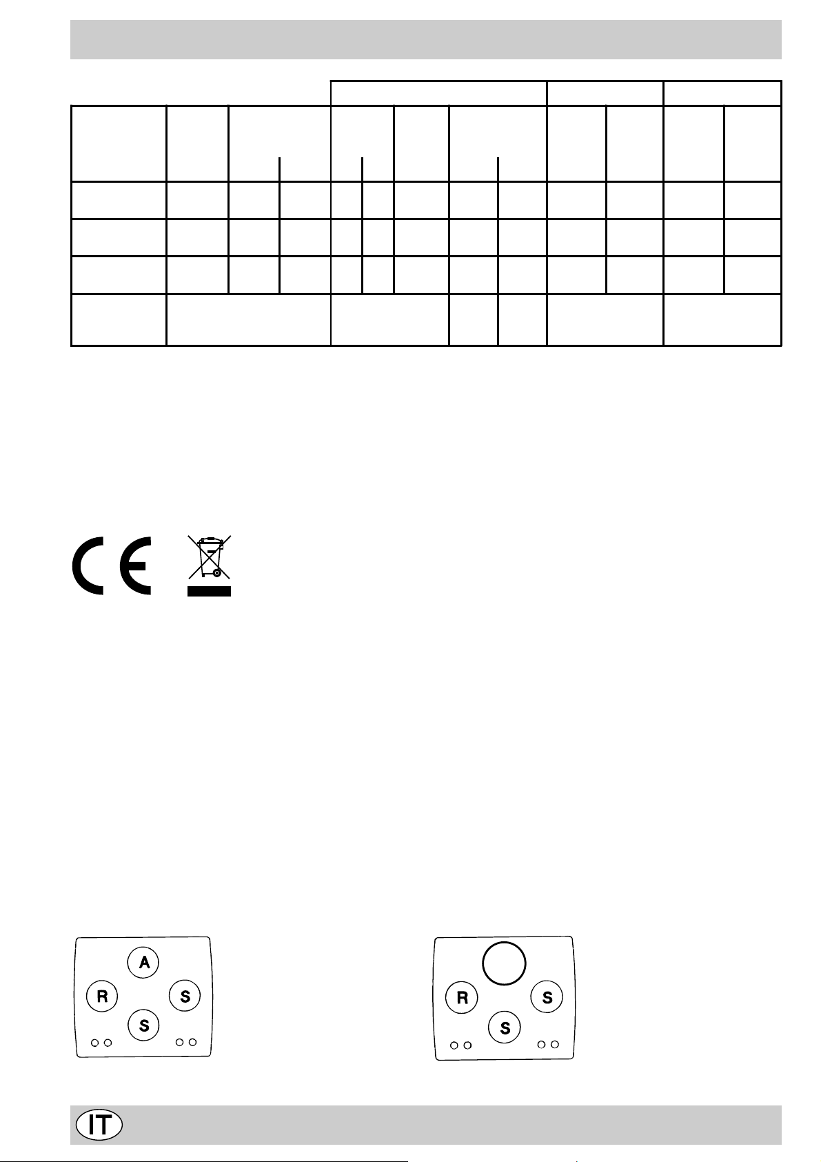
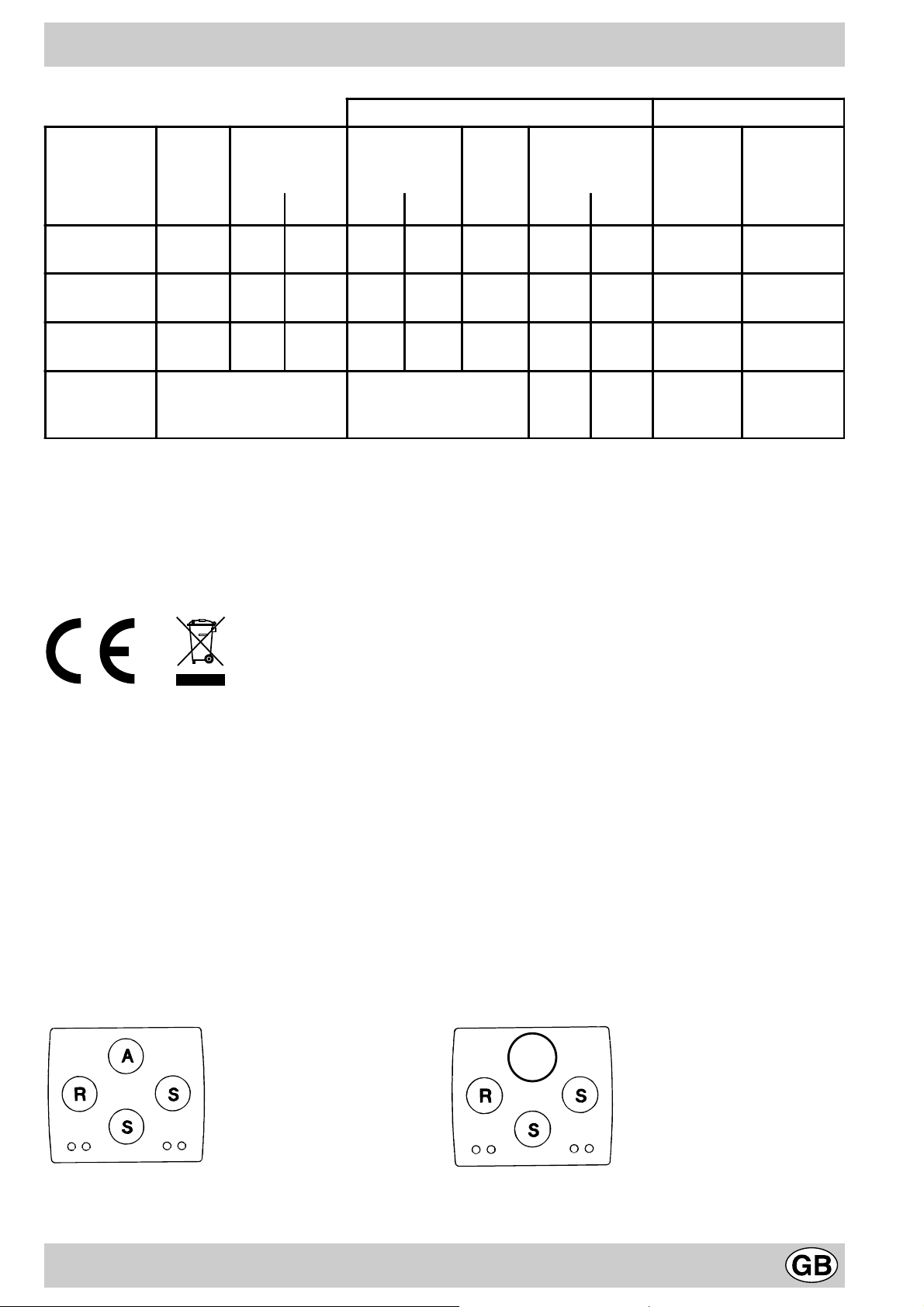
Caratteristiche dei bruciatori ed ugelli
Tabella 1 Gas liquido Gas naturale Gas città
Bruciatore Diametro
(mm)
Rapido
(Grande) (R)
Semi Rapido
(Medio) (S)
Ausiliario
(Piccolo) (A)
Pressioni di
alimentazione
100 3.00 0.70 41 39 86 218 214 116 286 285 680
75 1.65 0.40 30 28 64 120 118 96 157 185 374
55 1.00 0.40 30 28 50 73 71 71 95 145 227
Potenza termica
kW (p.c.s.*)
Nomin. Ridot. (1) (mm) *** ** (mm) (mm)
Nominale (mbar)
Minima (mbar)
Massima (mbar)
By-pass
1/100
(mm)
Ugello
1/100
Portata *
28-30
20
35
g/h
37
25
45
Ugello
1/100
Portata *
l/h
20
17
25
Ugello
1/100
Portata *
l/h
8
6
15
* A 15°C e 1013 mbar-gas secco
** Propano P.C.S. = 50,37 MJ/kg
*** Butano P.C.S. = 49,47 MJ/kg
Naturale P.C.S. = 37,78 MJ/m3
Città P.C.S. = 15,87 MJ/m3
(1) Solo per apparecchi con dispositivo di sicurezza contro le fughe di gas (riferimento F).
Attenzione: Conformemente alla Direttiva CEE 90/396 l’adattabilità al Gas Città è consentita solo per apparecchi con
dispositivo di sicurezza contro le fughe di gas (riferimento F).
Per la trasf ormazione a gas città, richiedere il kit ugelli presso un centro di assistenza Tecnica Merloni Elettrodomestici.
Questa apparecchiatura è conforme alle seguenti Direttive Comunitarie:
— 73/23/CEE del 19/02/73 (Bassa Tensione) e successive modificazioni;
— 89/336/CEE del 03/05/89 (Compatibilità Elettromagnetica) e successive modificazioni;
— 90/396/CEE del 29/06/90 (Gas) e successive modificazioni;
— 93/68/CEE del 22/07/93 e successive modificazioni.
— 2002/96/CE
La direttiva Europea 2002/96/CE sui rifiuti di apparecchiature elettriche ed elettroniche (RAEE), prevede che gli elettro-
domestici non debbano essere smaltiti nel normale flusso dei rifiuti solidi urbani. Gli apparecchi dismessi devono
essere raccolti separatamente per ottimizzare il tasso di recupero e riciclaggio dei materiali che li compongono ed
impedire potenziali danni per la salute e l’ambiente. Il simbolo del cestino barrato è riportato su tutti i prodotti per
ricordare gli obblighi di raccolta separata.
Per ulteriori informazioni, sulla corretta dismissione degli elettrodomestici, i detentori potranno rivolgersi al servizio
pubblico preposto o ai rivenditori.
TD 640… TD 631…
8
Congratualtions on choosing an Ariston appliance, which you will find is dependable and easy to use . W e recommend
that you read this manual for best performance and to extend the life of your appliance. Thank you.
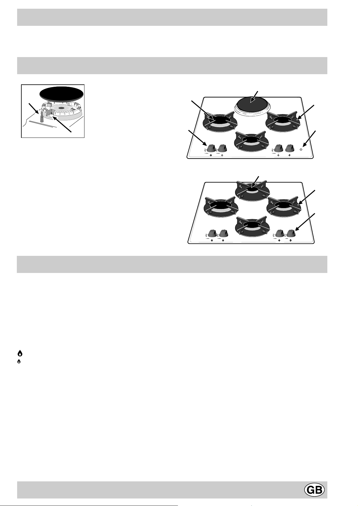
Close-up View
G
F
A
B
D
A. Gas Burners
B. Support Grid for Cookware
C. Control Knobs for Gas Burners and Electric Hot
Plate
D. Ignitor for Gas Burners (only on certain models)
E. Ignition Button for Gas Burners (only on certain
models)
F. Safety Device (only on certain models) — Activates if
the flame accidentally goes out (spills, drafts, etc.),
interrupting the delivery of gas to the burner.
G. Electric Hot Plate (only on certain models)
H. Indicator Light for Electric Hot Plate (only on certain
models)
How T o Use Y our Appliance
The position of the corresponding gas burner is indicated
on each control knob.
Gas Burners
The burners differ in size and power. Choose the most
appropriate one for the diameter of the cookware being
used.
The burner can be regulated with the corresonding control
knob by using one of the following settings:
• Off
High
Low
T o turn on one of the burner s, place a lighted match or
lighter near the burner, press the knob all the way in and
turn in the counter-clockwise direction to the «High» setting.
On those models fitted with a safety device (F), the
knob must be pressed in for about 6 seconds until the
device that keeps the flame lighted warms up .
C
1
6
2
5
4
3
H
A
B
C
On those models fitted with an ignitor (D), to light a
burner, simply press the corresponding knob all the way
in and then turn it in the counter-clockwise direction to the
«High» setting, keeping it pressed in until the burner lights.
Caution: If the burner accidently goes out, turn off the
gas with the control knob and try to light it again after
waiting at least 1 minute.
To turn off a burner, turn the knob in the clockwise
direction until it stops (it should be on the “•” setting).
Electric Hot Plate (only on certain models)
The hot plate can be: «normal» and «fast». The latter can
be identified by a red boss in the center of the hot plate
itself.
The hot plate can be regulated by turning the
corresponding knob in the clockwise or counter-clockwise
direction to any one of the 6 different settings:
0 Off
1 Low
2-5 Medium
6 High
The section entitled, «Practical Cooking Advise», provides
information on the recommended settings for various types
of food or cooking processes.
When the knob is on any of the settings other than «Off»,
the «H» operating light comes on.
9
How to Keep Your Cooktop in Shape
Before cleaning or performing maintenance on your
appliance, disconnect it from the electrical power supply.
To extend the life of the cooktop, it is absolutely
indispensable that it be cleaned carefully and
thoroughly on a frequent basis, keeping in mind the
following:
· Do not use steam equipment to clean the appliance.
• Enameled and glass parts must be washed with
lukewarm water without using abrasive powders or
corrosive substances that could damage them;
• The removable parts of the burners should be washed
frequently with warm water and soap, making sure to
remove caked-on substances;
• On cooktops with automatic ignition, the end of the
electronic ignition device must be cleaned carefully and
frequently, making sure that the gas holes are not
clogged;
• the top must be cleaned with glass cleaning products.
Avoid using abrasive products and abrasive sponges
that could scratch the glass.
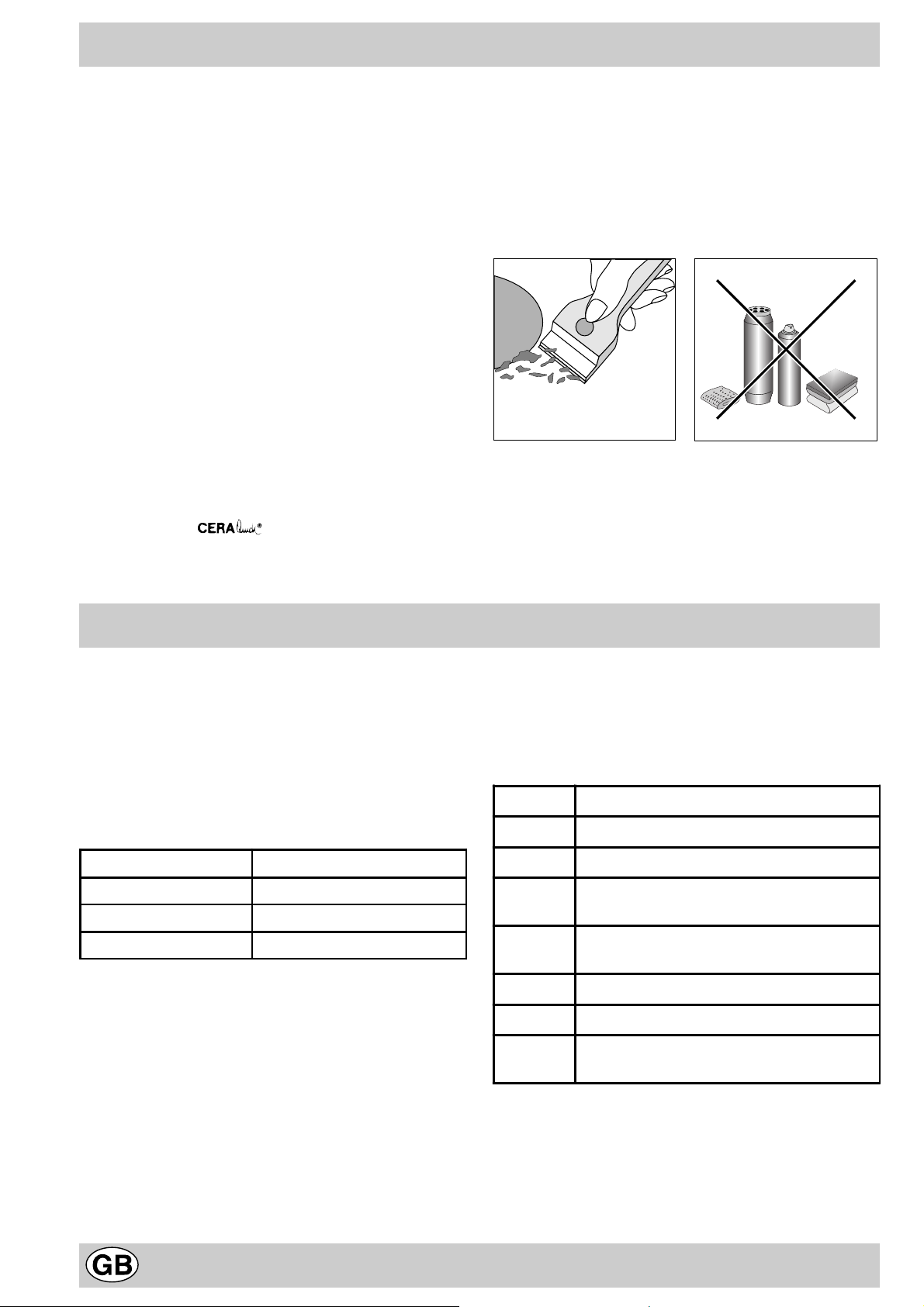
• the glass surface should be cleaned regularly with a
soultion of warm water and a non-abrasive detergent.
First, remove all food b uildup or grease with a cleaning
scraper , e.g. (not supplied) (Fig. A).
Clean the cooking surface when it is still warm with a
suitable cleaning product, then rub with a damp cloth
and dry. Sugar or foods with a high sugar content that
have melted onto the surface must be removed
immediatley with a scraper while the cooking surf ace
is still hot. Do not use abrasive sponges or cleaning
products under any circumstances. This holds true for
chemically aggressive cleaners, like oven spra ys and
stain removers (Fig. B);
Fig. A Fig. B
Greasing the Taps
The taps may jam in time or they ma y become difficult to
turn. If so , the tap itself must be replaced.
N.B.: This operation m ust be performed by a technician
authorised by the manufacturer .
Practical Advice
Practical Advise on Using the Burners
For best performance, f ollo w these general guidelines:
• Use the appropriate cookware for each burner (see
table) in order to prevent the flame from reaching the
sides of the pot or pan;
• Alwasy use cookware with a flat bottom and keep the
lid on;
• When the contents come to a boil, turn the knob to
«Low».
Burner ø Cookware diameter (cm)
Fast (R) 24 — 26
Semi Fast (S) 16 — 20
Auxiliary (A) 10 — 14
To identify the type of burner, refer to the designs in the
section entitled, «Burner and Nozzle Specifications».
Practical Advice on Using the Electric Hot Plates
In order to avoid heat loss and damage to the hot plate,
use cookware with a flat bottom the diameter of which is
not less than that of the hot plate.
Setting Normal or Fast Plate
0 Off
1 Cooking vegetables, fish
2
3
4
5
6
Cooking potatoes (using st eam) soup s,
chickpeas, beans.
Continuing the cook ing o f lar ge quant it ies
of food, minestrone
For roasting (average)
For roasting (abov e averag e)
For browning and reach ing a bo il in a
short time.
Before using the hot plates for the first time, you
should heat them at maximum temperature for
approximately 4 minutes, without any pans. During
this initial stage, their protective coating hardens and
reaches its maximum resistance.
10

Is there a problem?
It may occur that the cooktop does not function or does
not function properly . Before calling customer service for
assistance, lets see what can be done.
First of all, check to see that there are no interruptions in
the gas and electrical supplies, and, in particular, that the
gas valves f or the mains are open.
The burner does not light or the flame is not uniform
around the burner.
Check to make sure that:
• The gas holes on the burner are not clogged;
• All of the movable parts that make up the burner are
mounted correctly;
• There are no draughts around the cooking surface.
The flame does not stay lighted on the model with
the safety device.
Check to make sure that:
• You press the knob all the way in;
• You keep the knob pressed in long enough to activate
the safety device .
• The gas holes are not clogged in the area
corresponding to the safety device .
Safety Is a Good Habit to Get Into
The burner does not remain on when set to «Low».
Check to make sure that:
• The gas holes are not clogged.
• There are no draughts near the cooking surface.
• The minimum has been adjusted correctly (see the
section entitled, «Minimum Regulation»).
The cookware is not stable.
Check to make sure that:
• The bottom of the cookware is perfectly flat.
• The cookware is centered correctly on the burner.
• The support grids have not been inverted.
If, despite all of these checks, the cooktop does not
function properly and problem persists, call the nearest
Merloni Elettrodomestici Customer Service Centre,
informing them of:
— The type of prob lem.
— The abbre viation used to identify the model (Mod. …) as
indicated on the warranty.
Never call upon technicians not authorized by the
manufacturer, and refuse to accept spare parts that are
not original.
To maintain the EFFICIENCY and SAFETY of this appliance, we recommend:
• call only the Service Centers authorized by the manufacturer
• always use original Spare Parts
• This manual is for a class 3 built-in cooktop.
• This appliance is designed for non-professional use in
the home and its features and technical characteristics
must not be modified.
• These instructions are only valid for the countries the
symbols for which appear on the manual and the serial
plate.
• The electrical system of this appliance is safe only when
it is correctly connected to an adequate earthing
system, as required by current safety standards.
Prevent children and the disabled from coming into
contact or having access to the following, as the y
are possible sources of danger:
— The controls and the appliance in general;
— The packaging (plastic bags, polystyrene, nails, etc.);
— The appliance, during and immediately after use given
the heat generated by its use;
— The appliance when no longer in installed (in this case,
all potentially dangerous parts must be made safe).
— Exposure to atmospheric agents (rain, sun);
— Using flammable liquids nearby;
— Using adaptors, multiple outlet plugs and/or extensions;
— Using unstable or deformed cookware;
— The top made is resistant to sudden temperature
changes and shocks. However, if it is struck with
pointed utensils or objects such as cutting knives,
it may crack or break. If this occurs, disconnect
the appliance immediately from the power supply
and contact an authorised service centre.
— Trying to install or repair the appliance without the
assistance of qualified personnel.
The assistance of qualified personnel must be called
upon in the following cases:
— Installation (in accordance with the manufacturer’s
instructions);
— When in doubt about the operation of the appliance;
— Replacement of the electrical outlet becuase it is
incompatible with the plug.
The following should be av oided:
— Touching the appliance with wet parts of the body;
— Using the appliance with bare feet;
— Pulling on the appliance or the power supply cord to
disconnect them from the electrical outlet;
— Improper and/or dangerous use;
— Obstructing the ventilation or heat dissipation slots;
— Allowing the power supply cord of small appliances to
come into contact with the hot parts of the cooktop;
Contact service centers authorized by the
manufacturer in the following cases:
— When in doubt about the condition of the appliance
after having removed the pac king;
— Damage to or replacement of the power supply cord;
— In the case of a breakdown or malfunction: ask for
original spare parts.
11
It is recommended that you follow the guidelines
below:
— Only use the appliance to cook food, avoiding all other
uses;
— Check the condition of the appliance after it has been
unpacked;
— Disconnect the appliance from the power supply in the
event of malfunction and always before cleaning or
maintenance;
Installation Instructions for b uilt-in
— When not in use, disconnect the appliance from the
power supply and turn off the gas valve (if present);
— Always check to make sure that the control knobs are
on the “•”/”o” setting when the appliance is not in use;
— Cut the power supply cord after disconnecting it from
the electrical mains when you decide to no longer use
the appliance.
• The manufacturer will not be held liable for any
damages arising out of : incorrect installation or
improper, incorrect or unreasonab le use..
The following instructions are intended for the installer so
that the installation and maintenance procedures may be
followed in the most professional and expert manner
possible. Important: Disconnect the appliance fr om the
electrical supply before performing an y maintenance
or regulation upkeep work.
Positioning the Cooktop
Important: this unit may be installed and used only in
permanently ventilated rooms in accordance with British
Standard Codes Of Practice: B .S. 6172 / B.S. 5440, Par.
2 and B.S. 6891 Current Editions. The following
requirements must be observed:
a) The room must be fitted with a ventilation system which
vents smoke and gases from comb ustion to the outside.
This must be done by means of a hood or electric
ventilator that turns on automatically each time the hood
is operated.
In a chimney stack or branched flue. Directly to the Outside
(exclusively for cooking appliances)
b) The room must also allow for the influx of the air needed
for proper combustion. The flow of air for combustion
purposes must not be less than 2 m³/h per kW of installed
capacity . The supply of said air can be effected b y means
of direct influx from the outside through a duct with a
inner cross section of at least 100 cm² which must not be
able to be accidentally bloc ked. Those appliances which
are not fitted with a safety device to prevent the flame
from accidentally going out must have a ventilation
opening twice the size otherwise required, i.e. a minimum
of 200cm² (Fig. A). Otherwise, the room can be vented
indirectly through adjacent rooms fitted with ventilation
ducts to the outside as described above, as long as the
adjacent rooms are not shared areas, bedrooms or
present the risk of fire (Fig. B).
Detail A Adjacent Room to be
Room Vented
A
Examples of ventilation holes Enlarging the ventilation slot
for comburant air . between window and floor.
Fig. A Fig. B
c) Intensive and prolonged use of the appliance may ne-
cessitate supplemental ventilation, e.g. opening a window
or increasing the power of the air intake system (if
present).
d) Liquidified petroleum gases are heavier than air and, as
a result, settle downwards. Rooms in which LPG tanks
are installed must be fitted with ventilation openings to
the outside in order to allow the gas to escape in the
event of a leak. Theref ore, LPG tanks, whether empty or
partially full, must not be installed or stored in rooms or
spaces below ground lev el (cellars, ect.). It is also a good
idea to keep only the tank currently being used in the
room, making sure that it is not near sources of heat
(ovens, fireplaces , stoves, etc.) that could raise the internal
temperature of the tank above 50°C .
Installation of Built-in Cooktops
The appliance can be installed next to furniture units which
are no taller than the top of the cooker hob. The wall in
direct contact with the back panel of the cooker must be
made of non-flammable material. During operation the
back panel of the cooker could reach a temperature of
50°C above room temperature. For proper installation of
the cooker, the following precautions must be taken:
a) If the cabinet(s) located next to the cooktop are higher
than the cooktop itself, the cabinet(s) must be installed
at least 600 mm from the edge cooktop;
b) Hoods must be installed in accordance with the
instructions contained in the installation manual for the
hoods themselves, and no less than 650 mm from the
12
cooktop;
c) The cabinets installed next to the hood must be located
at a height of at least 420 mm from the top, (as sho wn
in Fig. C).
HOOD
Min. mm.
600
mm.
420
Min.
mm. with hood
420
650
Min. mm.
min.
mm. without hood
700
min.
Fig. C
d) Should the cooktop be installed directly under a
cupboard, the latter should be at least 700 mm
(millimetres) from the top, as shown in Fig. C.
e) The dimensions of the cutout for the appliance must
be those indicated in the figure.
555 mm.
Front
Clamp Position f or
H=20mm top Back
N.B: Use the clamps contained in the «accessory kit.»
f) In the event the cooktop is not installed above a built-
in oven, a wood panel must be inserted as insulation.
This panel must be placed at least 20 mm from the
bottom of the cooktop itself.
Important: When installing the cooktop above a built-in
oven, the ov en should be placed on two wooden strips; in
the case of a joining cabinet surface, remember to leave
a space of at least 45 x 560 mm at the back.
55 mm.
Before f astening the cooktop in place, position the seal
(supplied) along the perimeter of the countertop, as
shown in the figure.
Clamps are provided to fasten the cooktop to counters
measuring from 20 to 40 mm in thickness. To fasten
the cooktop securely, it is recommended that all the
clamps be used.
Fastening Clamps — Assembly Diagram
Clamp Position f or Clamp Position f or
H=30mm top H=40mm top
45 mm.
560 mm.
475 mm.
When installing the cooktop above a built-in o ven without
forced ventilation, ensure that there are air inlets and
outlets for ventilating the interior of the cabinet adequately .
Gas Connection for Cooktop
The cooktop should be connected to the gas supply by an
authorized installer. During installation of this product it is
essential to fit an approved gas tap to isolate the supply
from the appliance for the conv enience of any subsequent
removal or servicing. Connection of the appliance to the
gas mains or liquid gas tanks must be carried out
according to the safety standards currently in force, and
only after it is ascertained that it is suitable for the type of
gas to be used. If not, follow the instructions indicated in
the section entitled, “Adapting the Cooktop for Different
Types of Gas”. If the cooktop is to be connected to tanks
containing liquid gas, use pressure regulators that comply
with current safety standards.
Important: To insure that the appliance operates safety,
13
the gas is regulated correctly and your appliance lasts
over time, mak e sure that gas pressure lev els comply with
the indications given in Table 1, “Nozzle and Burner
Specifications”.
Gas Connection to Non-flexible Pipe
(copper or steel)
Connection to the gas source must be done in such a way
as to not create any stress points at any part of the
appliance.
The appliance is fitted with an adjustable, «L» shaped
connector and a gasket for the attachment to the gas supply .
Should this connector have to be turned, the gasket must be
replaced (supplied with the appliance).
The gas feed connector to the appliance is a threaded,
male 1/2″ connector for round gas pipe.
Gas Connection to Flexible Steel Pipe
The gas feed connector to the appliance is a threaded,
male 1/2″ connector for round gas pipe. Only use pipes,
tubes and gaskets that comply with current safety codes .
The maximum length of the flexible pipes must not e xceed
2000 mm. Once the connection has been made, ensure
that the flexible metal tube does not touch any moving
parts and is not crushed.
Check the Seal
Once the appliance has been installed, make sure all the
connections are properly sealed, using a soapy water
solution. Ne v er use a flame .
Electrical Connection
The cooktops fitted with a tripolar electrical supply cord
are designed to be be used with alternating current
according to the indications on the rating plate located
under the cooktop. The earthing wire can be identified by
its yellow-green colour .
In the case of installation over a b uilt-in electric oven,
the electrical connections for the cooktop and oven
should be independent, not only for saf ety purposes, but
also to facilitate remov al of one or both in the future.
Electrical Connection for Gas Cooktop
Fit the supply cord with a standard plug for the demand
rate indicated on the rating plate or connect it directly to
the electrical mains. In the latter case , a single pole switch
must be placed between the appliance and the mains,
with a minimum opening between the contacts of 3 mm in
compliance with current safety codes (the earthing wire
must not be interrupted by the switch). The pow er supply
cord must be positioned so that it does not reach a temperature in excess of 50°C above room temperature at
any point.
Before making the actual connection, make sure that:
• The fuse and electrical system can withstand the load
required by the appliance;
• That the electrical supply system is equiped with an
efficient earth hook-up according to the norms and
regulations prescribed by law;
• That the plug or switch is easily accessible.
Important: the wires in the mains lead are coloured in
accordance with the following code:
Green & Yellow — Earth
Blue — Neutral
Brown — Live
As the colours of the wires in the mains lead may not
correspond with the coloured markings identifying the
terminals in your plug, proceed as follows:
Connect the Green & Yellow wire to the terminal marked
“E” or or coloured Green or Green & Yellow.
Connect the Brown wire to the terminal marked “L” or
coloured Red.
Connect the Blue wire to the terminal marked “N” or
coloured Black.
Adapting the Cooktop for Different Types of Gas
To adapt the cooktop to a different type of gas than that
for which it was designed, (see the stick er under the hob
or on the packaging), the burner nozzles must be changed,
as follows:
• Remov e the pan supports and slide the burners out of
the cooktop.
• Unscre w the nozzles using a 7mm socket wrench and
replace them with those for the new type of gas. (See
table 1, “Burner and Nozzle Specifications”).
• Reassemble the parts following the instructions in
reverse order.
• On completing the operation, replace the old r ating label
with the one showing the new type of gas; the sticker
is available from our Service Centres.
If the gas pressure is different than that prescribed, a
pressure regulator must be installed at the source, in
compliance with national standards governing the use of
piped gas regulators.
Regulation of Air Supply to the Burner
The burners do not need a primary air regulator.
Minimum Regulation
Minimum regulation.
• Turn the gas valve to minimum.
• Remove the knob and turn the regulator screw
(positioned either on the side of the top or inside the
shaft) clockwise until the flame becomes small but
regular.
N.B.: In the case of liquid gas, the regulation screw must
be fully screwed in (clockwise).
• Make sure that, when the knob is turned rapidly high
to low , the flame does not go out.
• In the event of a malfunction on appliances with the
security device (thermocouple) when the gas supply
is set at minimum, increase the minimum supply lev els
using the regulator screw .
Once the adjustment has been made, apply sealing wax,
or a suitable substitute, to the old seals on the by-pass .
14
Burners and Nozzle Specifications
Table 1 Liquid Gas Natural Gas
Burner Diameter
(mm)
Fast
(Large) (R)
Semi Fast
(Medium) (S)
Auxiliary
(Small) (A)
Supply
pressures
* At 15°C and 1013 mbar-dry gas
** Propane P.C.S. = 50.37 MJ/kg.
*** Butane P.C.S . = 49.47 MJ/kg.
Natural P.C.S. = 37.78 MJ/m
(1) Only for appliances with the security device (Ref. F).
100 3.00 0.7 41 39 86 218 214 116 286
75 1.65 0.4 30 28 64 120 118 96 157
55 1.00 0.4 30 28 50 73 71 71 95
Thermal Power
kW (p.c.s.*)
Nom. Red. (1) (mm) *** ** (mm)
Nominal (mbar)
Minimum (mbar)
Maximum (mbar)
By-pass
1/100
(mm)
3
Nozzle
1/100
28-30
20
35
Flow*
g/h
37
25
45
Nozzler
1/100
Flow*
l/h
20
17
25
This appliance complies with the following European Economic Community directives:
— 73/23/EEC of 19/02/73 (Low Voltage) and subsequent modifications;
— 89/336/EEC of 03/05/89 (Electromagnetic Compatibility) and subsequent modifications;
— 90/396/EEC of 29/06/90 (Gas) and subsequent modifications;
— 93/68/EEC of 22/07/93 and subsequent modifications.
— 2002/96/EC
The European Directive 2002/96/EC on W aste Electrical and Electronic Equipment (WEEE), requires that old household
electrical appliances must not be disposed of in the normal unsorted municipal waste stream. Old appliances must be
collected separately in order to optimise the recovery and recycling of the materials they contain and reduce the impact
on human health and the environment. The crossed out “wheeled bin” symbol on the product reminds you of your
obligation, that when you dispose of the appliance it must be separately collected.
Consumers should contact their local authority or retailer for information concerning the correct disposal of their old
appliance.
TD 640… TD 631…
15

Merci d’avoir choisi un produit Ariston, fiable et facile à utiliser. Pour mieux le connaître et l’utiliser le plus longtemps
possible, nous vous conseillons de lire attentivement ce livret. Merci.
Vu de près
G
F
A
B
D
A. Brûleurs gaz
B. Grilles support de casseroles
C. Manettes de commande des brûleurs gaz ou des
plaque électriques
D. Bougie d’allumage des brûleurs gaz (présente
uniquement sur certains modèles)
E. Bouton d’allumage des brûleurs gaz (présent
uniquement sur certains modèles)
F. Dispositif de sécurité (n’existe que sur certains
modèles) — Intervient en cas d’extinction accidentelle
de la flamme (débordement de liquides, courants d’air ,
…) en interrompant automatiquement l’arrivée de gaz.
G. Plaque électriques (présent uniquement sur certains
modèles)
H. Voy ant de f onctionnement des plaque électriques
(présent uniquement sur certains modèles)
Comment l’utiliser
Sur chaque manette il y a indication de la position du brûleur
gaz correspondant.
Brûleurs gaz
Ils ont des dimensions et des puissances différentes.
Choisissez-en un en fonction du diamètre de la casserole
utilisée.
Pour le réglage du brûleur choisi, servez-v ous de la manette
correspondante, comme suit:
• Eteint
Maximum
Minimum
Pour allumer un brûleur, approchez une flamme ou un
allume-gaz, appuyez à fond sur la manette correspondante
et tournez-la dans le sens contraire des aiguilles d’une montre
jusqu’à la position: puissance maximum.
Pour les modèles équipés de dispositif de sécurité «F«,
appuyez sur la manette pendant 6 secondes environ jusqu’à
ce que le dispositif gardant automatiquement la flamme
allumée se réchauffe.
Pour les modèles équipés de bougie d’allumage «D«,
pour allumer le brûleur choisi, appuyez d’abord à fond sur la
manette correspondante et tournez-la ensuite dans le sens
contraire des aiguilles d’une montre jusqu’à la position
puissance maximum, continuez à appuyer jusqu’à ce qu’il y
ait allumage.
C
1
6
2
5
4
3
H
Conseil: en cas d’extinction accidentelle de la flamme du
brûleur, fermez la manette de commande et ne tentez de
rallumer qu’au bout d’une minute au moins.
Pour éteindre le brûleur tournez la manette dans le sens
des aiguilles d’une montre jusqu’à son point d’arrêt
(correspondant au symbole “•”).
Plaque électriques (uniquement sur certains modèles)
Elles peuvent avoir: «normales» ou «rapides», ces dernières
se distinguent des autres par la pastille rouge qu’elles ont
au centre.
Pour leur réglage , tournez la manette correspondante dans
le sens des aiguilles d’une montre ou dans le sens
contraire, 6 positions sont possibles:
0 Eteint
1 Puissance minimum
2÷5 Puissances intermédiaires
6 Puissance maximum
Le chapitre «Conseils d’utilisation pratiques» vous indique
les correspondances entre les positions indiquées sur les
manettes et une bonne utilisation des plaques.
T oute position de la manette autre que la posiiton «éteint»
entraîne l’allumage du voy ant de f onctionnement «H«.
16
Comment le garder en forme
Avant toute opér ation, coupez l’alimentation électrique de
l’appareil.
Pour prolonger la durée de vie de v otre table nettoyezla fréquemment, en n’oubliant pas que:
· pour le nettoyage, ne pas utiliser d’appareils à
vapeur
• les parties émaillées et en verre doivent être lavées à
l’eau tiède sans utiliser de poudres récurantes ou de
produits corrosifs qui pourraient les abîmer;
• les pièces amovibles des brûleurs doivent être lavées
souvent avec de l’eau chaude et du détergent en
veillant à éliminer toute incrustation possible;
• pour les tables équipées d’un dispositif d’allumage
automatique, procédez à un nettoyage fréquent de la
partie terminale des dispositifs d’allumage électronique
instantané en vérifiant que les orifices de sortie du gaz
ne soient pas bouchés;
• le plan de cuisson doit être nettoyé avec un produit
pour le nettoyage des verres. N’utilisez en aucun cas
des éponges ou produits abrasifs, qui pourraient ray er
le verre.
• nettoyez régulièrement la surface de la table en utilisant
une solution d’eau tiède et de détergent non abrasif.
Eliminez tout d’abord tous restes d’aliments et toutes
éclaboussures de graisse à l’aide d’un racloir comme
par exemple (n’étant pas fourni avec
l’appareil) (Fig. A).
Nettoyez la table de cuisson quand elle est tiède;
utilisez un produit de nettoyage approprié, frottez av ec
un chiffon humide et essuyez. Sucre ou des aliments
à haut contenu en sucre doivent être aussitôt netto yés
quand la zone de cuisson est encore chaude à l’aide
d’un racloir. N’utilisez jamais d’éponges ou de produits
abrasifs, ni de détergents chimiques agressifs tels que
par ex emple les produits en atomiseur pour four ou les
produits détachants (Fig. B);
Fig. A Fig. B
Graissage des robinets
Il peut arriver qu’au bout d’un certain temps, un robinet se
bloque ou tourne difficilement. Il f aut alors le remplacer.
N.B.: Cette opération doit être effectuée par un
technicien agréé par le fabricant.
Conseils d’utilisation
Conseils pratiques pour l’utilisation des brûleurs
Pour obtenir un maximum de rendement, n’oubliez pas
de:
• utiliser des casseroles appropriées pour chaque
brûleur (voir tableau), vous éviterez ainsi que les
flammes ne dépassent du fond des casseroles.
• utiliser toujours des casseroles à fond plat et avec
couvercle.
• au moment de l’ébullition, tourner la manette jusqu’à
la position minimum.
Brûleur ø Diamètre récipients (c m)
Rapide (R) 24 – 26
Semi-Rapide (S) 16 – 20
Auxiliaire (A) 10 – 14
Pour distinguer le type de brûleur reportez-vous aux
dessins figurant dans le paragraphe «Caractéristiques des
brûleurs et des injecteurs»
Conseils pratiques pour l’utilisation des plaques
électriques
Afin d’éviter toute déperdition de chaleur et d’endommager
la plaque, utilisez des casseroles à fond plat et d’un
diamètre au moins égal à celui de la plaque.
Position Plaqu e normal e ou rapi de
0
1
2
3
4
5
6
Eteint
Cuisson de légumes verts, poissons
Cuisson de pommes de terre (à la
vapeur) soupes, pois chiches, haricots
Pour continuer la cuisson de grandes
quantités d’aliments, minestrone
Rôtir (moyen)
Rôtir (fort)
Rissoler ou rejoindre l’ébullition en peu
de temps
Avant d’utiliser vos plaques de cuisson pour la
première fois, faites-les chauffer pendant 4 minutes à
leur température maximum sans casserole. A u cours
de cette phase initiale, le revêtement protecteur dur cit
et atteint sa résistance maximum.
17

Quelque chose ne va pas?
Il peut arriver que la table ne fonctionne pas ou ne
fonctionne pas très bien. A vant d’appeler le service aprèsvente, v o y ons ensemb le que faire.
Vérifiez avant tout qu’il n’y ait pas de coupure de gaz ou
de courant, et que les robinets du gaz en amont de la
table soient bien ouverts.
Le brûleur ne s’allume pas ou la flamme n’est pas
uniforme.
Av ez-vous contrôlé si:
• les orifices de sor tie du gaz ne sont pas par hasard
bouchés.
• les pièces amovibles composant le brûleur sont bien
montées correctement.
• il y a des courants d’air dans les environs de la table.
La flamme ne reste pas allumée dans les versions
avec dispositif de sécurité.
Av ez-vous contrôlé si:
• vous avez bien appuyé à fond sur la manette.
• vous avez bien appuyé à f ond sur la manette pendant
un laps de temps suffisant pour permettre au dispositif
de sécurité d’être branché.
• les orifices de sortie du gaz situés en face du dispositif
de sécurité ne sont pas par hasard bouchés.
Le brûleur s’éteint quand il est réglé sur la position
de minimum.
Avez-vous contrôlé si:
• les orifices de sor tie du gaz ne sont pas par hasard
bouchés.
• il y a des courants d’air dans les environs de la table.
• Le minimum n’a pas été correctement réglé (Voir
paragraphe «Réglage minimum»).
Les casseroles sont instables.
Avez-vous contrôlé si:
• Le fond de la casserole est parfaitement plat.
• la casserole est bien placée au centre du brûleur.
• Les grilles n’ont pas par hasard été inverties.
Si, malgré tous ces contrôles, votre table ne fonctionne
toujours pas et l’inconvénient persiste, appelez le Service
Après-vente Merloni Elettrodomestici le plus proche en
précisant:
— le type de panne.
— le sigle du modèle (Mod. …) indiqué dans le certificat de
garantie.
Ne faites jamais appel à des techniciens non agréés et
refusez toujours l’installation de pièces détachées non
originales…
La sécurité, une bonne habitude
Pour garantir l’efficacité et la sécurité de ce produit:
• adressez-vous exclusivement aus Centres d’assistance technique agréés
• demander toujours l’utilisation de pièces détachées originales.
• Ce livret concerne une table de cuisson à encastrer classe
3.
• Cet appareil a été conçu pour un usage non professionnel,
à domicile, ses caractéristiques ne peuvent être modifiées.
• Les instructions fournies ne sont applicables qu’aux pays
dont les symboles sont reportés dans la notice et sur la
plaquette d’immatriculation.
• La sécurité électr ique de cet appareil n’est garantie que si
ce dernier a été correctement raccordé à une installation
de mise à la terre efficace conforme aux normes de
sécurité..
Ce dernier pouvant représenter un danger, évitez que
des enfants ou des incapables aient accés:
— aux commandes et à l’appareil en général;
— aux emballages (sachets, polystyrène, clous etc.);
— à l’appareil, pendant et tout de suite après son
fonctionnement, à cause de la surchauffe;
— à l’appareil inutilisé dans ce cas il faut rendre inoffensives
les parties pouvant s’avérer dangereuses).
Evitez:
— de toucher l’appareil avec des parties du cor ps humides;
— de l’utiliser pieds nus;
— de tirer sur l’appareil ou sur le cordon d’alimentation pour
le débrancher de la prise de courant;
— toute opération inappropr iée ou dangereuse;
— de boucher les fentes d’aération ou de déperdition de la
chaleur;
— que le cordon d’alimentation de petits électroménagers
touchent à des parties chaudes de l’appareil;
— l’exposition aux agents atmosphériques (pluie, soleil);
— d’utiliser des liquides inflammables à proximité;
— d’utiliser des adaptateurs, des prises multiples et/ou des
rallonges;
— La table résiste aux sautes de température et aux chocs.
Cependant, elle peut se briser sous l’effet d’un choc
provoqué par un objet pointu, tel qu’un outil par
exemple. Dans ce cas, coupez immédiatement
l’alimentation et contactez un centre de Service AprèsVente agréé pour la réparation.
— toute tentative d’installation ou de réparation sans
l’intervention de personnel qualifié.
Faites toujours appel à des techniciens qualifiés dans
les cas suivants:
— installation (conforme aux instr uctions du fabricant);
— quand vous avez des doutes sur son fonctionnement;
— remplacement de la pr ise en cas d’incompatibilité avec la
fiche de l’appareil.
Faites appel aux centres de service après-vente agréés
par le fabricant dans les cas suivants:
— en cas de doute sur le bon état de l’appareil lors de son
déballage;
— endommagement ou remplacement du cordon
d’alimentation;
— en cas de panne ou de mauvais fonctionnement, exigez
des pièces détachées originales..
18
Effectuez les opérations suivantes:
— évitez toute opération autre que la cuisson;
— vér ifiez le bon état de l’appareil lors de son déballage;
— débranchez l’appareil de la prise de courant en cas de
mauvais fonctionnement et avant toute opération de
nettoyage ou d’entretien;
— quand il est inutilisé, débranchez-le de la prise et f ermez le
robinet du gaz (s’il y en a un de prévu);
Installation des tables à encastrer
Les instructions suivantes sont destinées à l’installateur
qualifié pour lui permettre d’effectuer correctement les
opérations d’installation, de réglage et d’entretien technique
conformément aux normes en vigueur.
Important: n’importe quelle opération de réglage,
d’entretien, etc…, doit être effectuée après avoir
débranché la prise de la table de cuisson.
Les appareils réglés en usine pour (voir la plaquette
d’immatriculation et la plaquette prédisposition gaz de
l’appareil):
gaz Naturel Catégorie II2E+3+ pour la France;
gaz Naturel Catégorie II2E+3+ pour la Belgique;
gaz Naturel Catégorie I2L pour la Hollande.
Un ultérieur réglage n’est donc pas nécessaire.
Conditions réglementaires d’installation (Pour la
France)
Le raccordement gaz devra être fait par un technicien qui
assurera la bonne alimentation en gaz et le meilleur réglage
de la combustion des brûleurs. Ces opérations d’installation,
quoique simples, sont délicates et primordiales pour que votre
table de cuisson vous rende le meilleur service. L ’installation
doit être effectuée conformément aux te xtes réglementaires
et règles de l’art en vigueur, notamment:
• Arrêté du 2 août 1977. Règles techniques et de sécurité
applicables aux installations de gaz combustibles et
d’hydro-carbures liquéfiés situées à l’intérieur des
bâtiments d’habitation et de leur dépendances.
• Norme DTU P45-204. Installations de gaz (anciennement
DTU n° 61-1-installations de gaz — Avril 1982 + additif n°1
Juillet 1984).
• Règlement sanitaire départemental.
— veillez à ce que les manettes soient toujours sur la position
“•”/”o” quand l’appareil est inutilisé;
— coupez le cordon d’alimentation après l’avoir débranché de
la prise quand vous décidez de ne plus utiliser votre
appareil.
• Le fabricant décline toute responsabilité en cas de
dommages dûs à: une mauvaise installation, à des usages
impropres, incorrects et déraisonnables.
En cas de cheminée ou conduit de fumée ramifié Directement à l’externe
(réservé aux appareils de cuisson)
b) La pièce doit être équipée d’un système permettant
l’apport d’air indispensable à une bonne combustion. La
quantité d’air comburant ne doit pas être inférieure à 2
m³/h par kW de puissance installée. Le système peut
être du type prélevant directement l’air de l’extérieur de
l’immeuble au moyen d’un conduit de vant av oir au moins
100 cm² de section utile et ne risquant pas d’être
accidentellement bouché. Pour les tables de cuisson
dépourvues de dispositif de sécurité en cas d’extinction
de la flamme, il faut prévoir des ouvertures d’aération
agrandies de 100%, le minimum prévu est de toute
manière de 200cm² (Fig. A). Ou bien du type prélevant
indirectement l’air de locaux adjacents équipés d’un
conduit d’aération vers l’e xtérieur comme sus indiqué et
qui ne soient pas des parties communes de l’immeuble,
des pièces à risque d’incendie ou des chambres à
coucher (Fig. B).
Détail A Local Local à
adjacent ventiler
Positionnement
Cet appareil peut être installé et fonctionner seulement dans
des locaux qui sont aérés en permanence, selon les
prescriptions des Normes:
— Pour la France selon les Normes Nationales en vigueur .
— Pour la Belgique NBN D51-003 et NBN D51-001 en
vigueur.
— Pour la Hollande NEN-1078 en vigueur.
Il faut observer les conditions suivantes:
a) La pièce doit prévoir un système d’évacuation vers
l’externe des fumées de combustion, réalisé au moyen
d’une hotte ou par ventilateur électrique qui entre
automatiquement en fonction dès que l’on allume
l’appareil.
A
Exemples d’ouverture de ventilation Agrandissement de la fissure entre
pour l’air comburant la porte et le sol
Fig. A Fig. B
c) En cas d’utilisation intensive et prolongée de l’appareil,
une aération supplémentaire pourrait être nécessaire;
dans ce cas, ouvrez une fenêtre ou augmentez la
puissance de l’aspiration mécanique si vous disposez
d’une hotte.
19
d) (Pour la F rance et la Belgique)
Les gaz de pétrole liquéfiés, plus lourds que l’air, se
déposent et stagnent vers le bas. Les locaux qui
contiennent donc des bidons de GPL doivent prévoir des
ouvertures vers l’extérieur afin de permettre l’évacuation
par le bas, des fuites éventuelles de gaz. Les bidons de
GPL, qu’ils soient vides ou partiellement pleins, ne devront
donc pas être installés ou déposés dans des locaux qui
se trouvent au dessous du niveau du sol (ca v es etc.).
Il est opportun de tenir dans le local, uniquement le bidon
que vous êtes en train d’utiliser , placé de façon à ne pas
être sujet à l’action directe des sources de chaleur (fours,
feux de bois, poêles etc.) pouvant lui faire atteindre des
températures dépassant 50°C.
Installation des tables à encastrer
Possibilité d’installation côte à côte a vec des meubles dont
la hauteur ne dépasse pas celle du plan de travail. La
paroi en contact avec la paroi postérieure de la cuisinière
doit être réalisée en matériel non inflammable. Pendant
le fonctionnement, la paroi postérieure de la cuisinière
peut atteindre une température de 50°C supérieure à celle ambiante. Il faut observer les précautions suivantes pour
une installation correcte de la cuisinière:
a) Les meubles adjacents ay ant une hauteur dépassant celle
du plan de travail, doivent être situés à au moins 110
mm du bord du plan.
b) Les hottes doivent être installées conformément aux
indications fournies par les notices d’instructions de ces
dernières et en tous cas, à au moins 650 mm de distance.
c) Positionner les éléments adjacents à la hotte à 420 mm.
au moins au-dessus de la table (Fig. C).
Avant de procéder à la fixation au plan de travail,
montez le joint (fourni) le long du périmètre de la table
comme illustré.
Des crochets de fixation sont prévus pour fixer le plan
sur des dessus de meuble de 20 à 40 mm d’épaisseur. Il
est conseillé d’utiliser tous les crochets fournis pour
obtenir une bonne fixation de la table.
Schéma de fixation des crochets
Position crochet pour Position crochet pour
top H=30mm top H=40mm
Devant
HOOD
Min. mm.
600
mm.
420
Min.
mm. with hood
420
650
Min. mm.
min.
mm. without hood
700
min.
Fig. C
d) Si la table est installée sous un élément suspendu, il faut
que ce dernier soit placé à au moins 700 mm (millimètres)
de distance du plan comme indiqué Fig. C.
e) La niche pratiquée dans le meuble devra avoir les
dimensions indiquées Fig.
555 mm.
55 mm.
475 mm.
Position crochet pour Derrière
top H=20mm
N.B: Utilisez les crochets inclus dans le «sachet accessoires»
f) Si la table de cuisson n’est pas installée au-dessus
d’un four encastré, il faut intercaler un panneau en bois
servant d’isolation. Ce dernier doit être installé à au
moins 20 mm. de distance du bas de la tab le .
Note: si la table de cuisson est installée au dessus d’un f our
encastré, il vaut mieux installer le four de façon à ce qu’il
repose sur deux cales en bois; si le plan d’appui est un plan
continu, ce dernier doit avoir à l’arrière une ouverture d’au
moins 45×560 mm.
45 mm.
560 mm.
20
Loading…
Перейти к контенту
Варочные панели Ariston
- Размер инструкции: 1,010.53 kB
- Формат файла: pdf
Если вы потеряли инструкцию от варочной панели Ariston TD 640 ES, можете скачать файл для просмотра на компьютере или печати.
Инструкция для варочной панели Ariston TD 640 ES на русском языке. В руководстве описаны возможности и полезные функции, а также правила эксплуатации. Перед использованием внимательно ознакомьтесь с инструкцией.
Чтобы не читать всю инструкцию вы можете выполнить поиск по содержимому внутри инструкции и быстро найти необходимую информацию. Рекомендации по использованию помогут увеличить срок службы варочной панели Ariston TD 640 ES. Если у вас появилась проблема, то найдите раздел с описанием неисправностей и способами их решения. В нем указаны типичные поломки и способы их решения.
Manuals.eu
- Manuals.eu
- Hotpoint-Ariston
- Home & Kitchen
- Hobs
- TD 640 ES (CH)
Free Manuals for Hotpoint-Ariston TD 640 ES (CH)
Manufacturer:Hotpoint-Ariston
Category:Home & Kitchen
Device:Hotpoint-Ariston TD 640 ES (CH)
Name:Instruction
Language:CatalàDeutschEnglishEspañolFrançaisItalianoNederlandsPortuguêsTürkçe
Pages:62
Size:2.75 MB
DescriptionHotpoint-Ariston TD 640 ES (CH) InstructionView Hotpoint-Ariston TD 640 ES (CH) Instruction (Català, Deutsch, English, Español, Français, Italiano, Nederlands, Português, Türkçe)
×
Copyright © Manuals.eu
Agreement
Privacy Policy
Contact us

- Детали
- Описание
- Дополнительные услуги
Детали
| Бренд / вароч. поверхности |
Hotpoint-Ariston |
|---|---|
| Тип панели |
газовая |
| Установка |
независимая |
| Материал поверхности |
нержавеющая сталь |
| Всего конфорок |
4 |
| Газовых конфорок |
4 |
| Ширина, см |
59 |
| Глубина, см |
51 |
| Расположение панели |
спереди |
| Газ-контроль |
да |
| Электроподжиг |
да |
| Ширина встраивания, см |
56 |
| Глубина встраивания, см |
49 |
| Решетки |
чугун |
| Количество конфорок |
4 |
| Цвет |
бежевый |
Варочная поверхность Hotpoint-Ariston TD 640 ES благодаря компактному размеру не займет много места. Конфорки обеспечат вам долгий срок службы. Установка варочной поверхности Hotpoint-Ariston TD 640 ES независимая. Уровень мощности регулируется с помощью переключателей.
Заказать звонок
В корзине нет никаких продуктов!