

AV SURROUND RECEIVER
AVR-3806
OPERATING INSTRUCTIONS

FCC INFORMATION (For US customers)
2 SAFETY PRECAUTIONS
1. PRODUCT
This product complies with Part 15 of the FCC Rules. Operation is
subject to the following two conditions: (1) this product may not cause
harmful interference, and (2) this product must accept any interference
received, including interference that may cause undesired operation.
2. IMPORTANT NOTICE: DO NOT MODIFY THIS PRODUCT
This product, when installed as indicated in the instructions contained
in this manual, meets FCC requirements. Modification not expressly
approved by DENON may void your authority, granted by the FCC, to
use the product.
3. NOTE
This product has been tested and found to comply with the limits for a
Class B digital device, pursuant to Part 15 of the FCC Rules. These
limits are designed to provide reasonable protection against harmful
interference in a residential installation.
This product generates, uses and can radiate radio frequency energy
and, if not installed and used in accordance with the instructions, may
cause harmful interference to radio communications. However, there
is no guarantee that interference will not occur in a particular
installation. If this product does cause harmful interference to radio or
television reception, which can be determined by turning the product
OFF and ON, the user is encouraged to try to correct the interference
by one or more of the following measures:
• Reorient or relocate the receiving antenna.
• Increase the separation between the equipment and receiver.
• Connect the product into an outlet on a circuit different from that
to which the receiver is connected.
• Consult the local retailer authorized to distribute this type of
product or an experienced radio/TV technician for help.
CAUTION:
TO REDUCE THE RISK OF ELECTRIC SHOCK, DO NOT
REMOVE COVER (OR BACK). NO USER-SERVICEABLE
PARTS INSIDE. REFER SERVICING TO QUALIFIED SERVICE
PERSONNEL.
The lightning flash with arrowhead symbol, within an
equilateral triangle, is intended to alert the user to the
presence of uninsulated “dangerous voltage” within the
product’s enclosure that may be of sufficient magnitude
to constitute a risk of electric shock to persons.
The exclamation point within an equilateral triangle is
intended to alert the user to the presence of important
operating and maintenance (servicing) instructions in the
literature accompanying the appliance.
WARNING:
TO REDUCE THE RISK OF FIRE OR ELECTRIC SHOCK, DO
NOT EXPOSE THIS APPLIANCE TO RAIN OR MOISTURE.
1. Read Instructions – All the safety and operating instructions should be
read before the product is operated.
2. Retain Instructions – The safety and operating instructions should be
retained for future reference.
3. Heed Warnings – All warnings on the product and in the operating
instructions should be adhered to.
4. Follow Instructions – All operating and use instructions should be
followed.
5. Cleaning – Unplug this product from the wall outlet before cleaning.
Do not use liquid cleaners or aerosol cleaners.
6. Attachments – Do not use attachments not recommended by the
product manufacturer as they may cause hazards.
7. Water and Moisture – Do not use this product near water – for
example, near a bath tub, wash bowl, kitchen sink, or laundry tub; in
a wet basement; or near a swimming pool; and the like.
8. Accessories – Do not place this product on an unstable cart, stand,
tripod, bracket, or table. The product may fall, causing serious injury
to a child or adult, and serious damage to the product. Use only with
a cart, stand, tripod, bracket, or table recommended by the
manufacturer, or sold with the product. Any
mounting of the product should follow the
manufacturer’s instructions, and should use a
mounting accessory recommended by the
manufacturer.
9. A product and cart combination should be moved
with care. Quick stops, excessive force, and
uneven surfaces may cause the product and cart
combination to overturn.
10. Ventilation – Slots and openings in the cabinet are provided for
ventilation and to ensure reliable operation of the product and to
protect it from overheating, and these openings must not be blocked
or covered. The openings should never be blocked by placing the
product on a bed, sofa, rug, or other similar surface. This product
should not be placed in a built-in installation such as a bookcase or
rack unless proper ventilation is provided or the manufacturer’s
instructions have been adhered to.
11. Power Sources – This product should be operated only from the type
of power source indicated on the marking label. If you are not sure of
the type of power supply to your home, consult your product dealer
or local power company. For products intended to operate from
battery power, or other sources, refer to the operating instructions.
12. Grounding or Polarization – This product may be equipped with a
polarized alternating-current line plug (a plug having one blade wider
than the other). This plug will fit into the power outlet only one way.
This is a safety feature. If you are unable to insert the plug fully into
the outlet, try reversing the plug. If the plug should still fail to fit,
contact your electrician to replace your obsolete outlet. Do not defeat
the safety purpose of the polarized plug.
13. Power-Cord Protection – Power-supply cords should be routed so that
they are not likely to be walked on or pinched by items placed upon
or against them, paying particular attention to cords at plugs,
convenience receptacles, and the point where they exit from the
product.
15. Outdoor Antenna Grounding – If an outside antenna or cable system
is connected to the product, be sure the antenna or cable system is
grounded so as to provide some protection against voltage surges
and built-up static charges. Article 810 of the National Electrical Code,
ANSI/NFPA 70, provides information with regard to proper grounding
of the mast and supporting structure, grounding of the lead-in wire to
an antenna discharge unit, size of grounding conductors, location of
antenna-discharge unit, connection to grounding electrodes, and
requirements for the grounding electrode. See Figure A.
16. Lightning – For added protection for this product during a lightning
storm, or when it is left unattended and unused for long periods of
time, unplug it from the wall outlet and disconnect the antenna or
cable system. This will prevent damage to the product due to
lightning and power-line surges.
17. Power Lines – An outside antenna system should not be located in
the vicinity of overhead power lines or other electric light or power
circuits, or where it can fall into such power lines or circuits. When
installing an outside antenna system, extreme care should be taken to
keep from touching such power lines or circuits as contact with them
might be fatal.
18. Overloading – Do not overload wall outlets, extension cords, or
integral convenience receptacles as this can result in a risk of fire or
electric shock.
19. Object and Liquid Entry – Never push objects of any kind into this
product through openings as they may touch dangerous voltage
points or short-out parts that could result in a fire or electric shock.
Never spill liquid of any kind on the product.
20. Servicing – Do not attempt to service this product yourself as opening
or removing covers may expose you to dangerous voltage or other
hazards. Refer all servicing to qualified service personnel.
21. Damage Requiring Service – Unplug this product from the wall outlet
and refer servicing to qualified service personnel under the following
conditions:
a) When the power-supply cord or plug is damaged,
b) If liquid has been spilled, or objects have fallen into the product,
c) If the product has been exposed to rain or water,
d) If the product does not operate normally by following the operating
instructions. Adjust only those controls that are covered by the
operating instructions as an improper adjustment of other controls
may result in damage and will often require extensive work by a
qualified technician to restore the product to its normal operation,
e) If the product has been dropped or damaged in any way, and
f) When the product exhibits a distinct change in performance – this
indicates a need for service.
22. Replacement Parts – When replacement parts are required, be sure
the service technician has used replacement parts specified by the
manufacturer or have the same characteristics as the original part.
Unauthorized substitutions may result in fire, electric shock, or other
hazards.
23. Safety Check – Upon completion of any service or repairs to this
product, ask the service technician to perform safety checks to
determine that the product is in proper operating condition.
24. Wall or Ceiling Mounting – The product should be mounted to a wall
or ceiling only as recommended by the manufacturer.
25. Heat – The product should be situated away from heat sources such
as radiators, heat registers, stoves, or other products (including
amplifiers) that produce heat.
SAFETY INSTRUCTIONS
FIGURE A
EXAMPLE OF ANTENNA GROUNDING
AS PER NATIONAL
ELECTRICAL CODE
ANTENNA
LEAD IN
WIRE
GROUND
CLAMP
ELECTRIC
SERVICE
EQUIPMENT
ANTENNA
DISCHARGE UNIT
(NEC SECTION 810-20)
GROUNDING CONDUCTORS
(NEC SECTION 810-21)
GROUND CLAMPS
POWER SERVICE GROUNDING
ELECTRODE SYSTEM
(NEC ART 250, PART H)
NEC — NATIONAL ELECTRICAL CODE
CAUTION
RISK OF ELECTRIC SHOCK
DO NOT OPEN
2 NOTE ON USE / OBSERVATIONS RELATIVES A L’UTILISATION
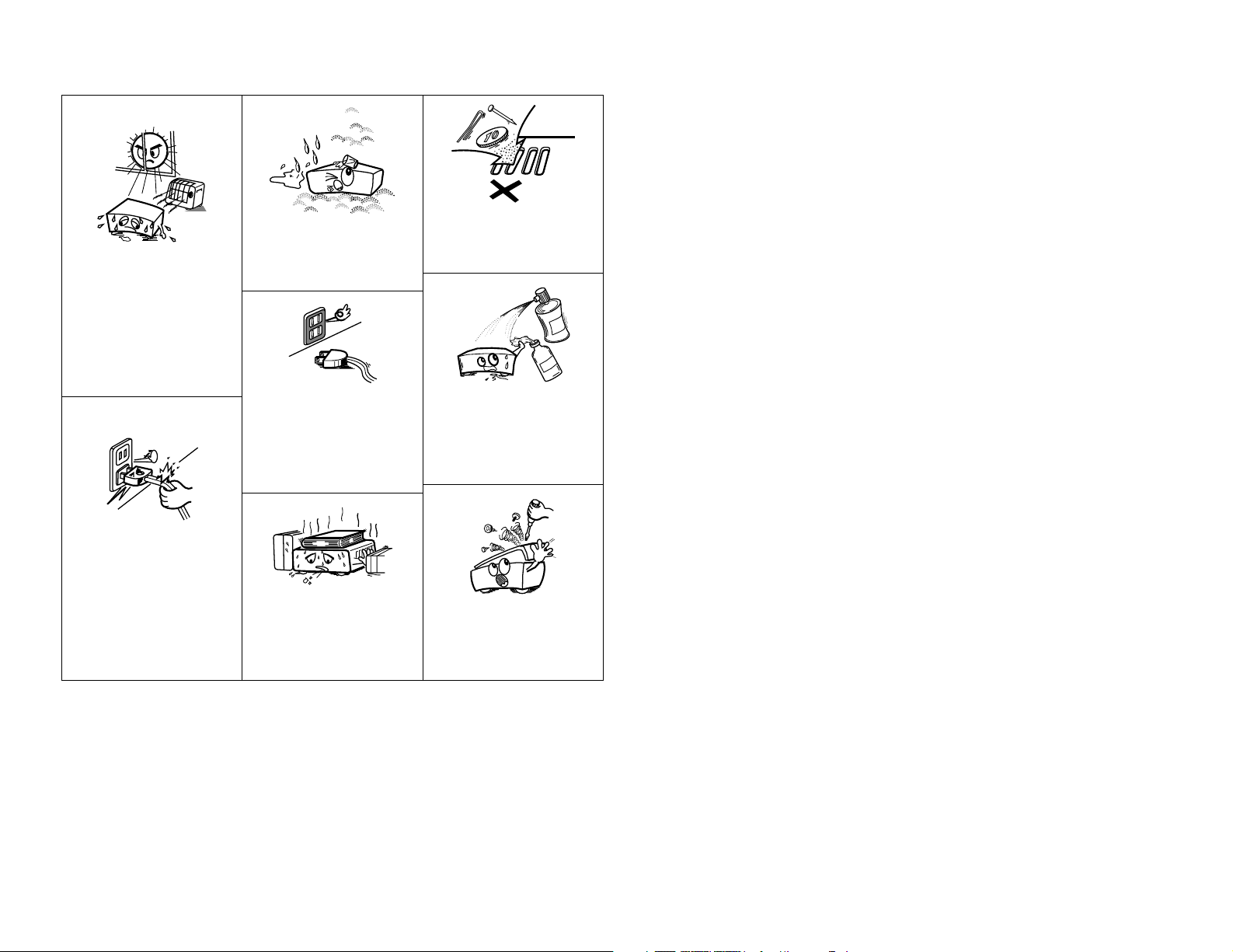
• Avoid high temperatures.
Allow for sufficient heat
dispersion when installed in a
rack.
• Eviter des températures
élevées.
Tenir compte d’une dispersion
de chaleur suffisante lors de
l’installation sur une étagère.
• Handle the power cord carefully.
Hold the plug when unplugging
the cord.
• Manipuler le cordon
d’alimentation avec
précaution.
Tenir la prise lors du
débranchement du cordon.
• Keep the apparatus free from
moisture, water, and dust.
• Protéger l’appareil contre
l’humidité, l’eau et la poussière.
• Unplug the power cord when
not using the apparatus for long
periods of time.
• Débrancher le cordon
d’alimentation lorsque l’appareil
n’est pas utilisé pendant de
longues périodes..
* (For apparatuses with ventilation holes)
• Do not obstruct the ventilation
holes.
• Ne pas obstruer les trous
d’aération.
• Do not let foreign objects into
the apparatus.
• Ne pas laisser des objets
étrangers dans l’appareil.
• Do not let insecticides,
benzene, and thinner come in
contact with the apparatus.
• Ne pas mettre en contact des
insecticides, du benzène et un
diluant avec l’appareil.
• Never disassemble or modify
the apparatus in any way.
• Ne jamais démonter ou modifier
l’appareil d’une manière ou
d’une autre.

Advanced Operation
Remote control unit
Operating DENON audio components ···························47, 48
Preset memory·····································································49
Operating a component stored in the preset memory ·····49 ~ 51
Learning function··································································52
System call ···········································································53
Punch through ······································································54
Setting the back light’s lighting time····································54
Setting the ambient light sensor ··········································54
Setting the brightness ··························································54
Resetting ··············································································55
Multi zone music entertainment system
Multi-zone playback using the ZONE2
and ZONE3 PREOUT terminals ············································56
Multi-zone playback using the SPEAKER terminals ·············57
Outputting a program source to amplifier, etc.,
in a ZONE2 room (ZONE2 SELECT mode)···························58
Outputting a program source to amplifier, etc.,
in a ZONE3 room (ZONE3 SELECT mode)···························58
Remote control unit operations during
multi-source playback ···························································58
Other function
Playing Super Audio CDs with DENON LINK·······················59
Multi-source recording / playback·········································60
Last function memory ··························································60
Initialization of the microprocessor·······································60
1
Getting Started
Contents
Getting Started
Thank you for choosing the DENON AVR-3806 Digital Surround A / V amplifier. This remarkable component has been engineered to
provide superb surround sound listening with home theater sources such as DVD, as well as providing outstanding high fidelity
reproduction of your favorite music sources.
As this product is provided with an immense array of features, we recommend that before you begin hookup and operation that you
review the contents of this manual before proceeding.
Accessories ··············································································2
Before using·············································································2
Cautions on installation ·························································3
Cautions on handling······························································3
Preparing the remote control unit ········································3
Inserting the batteries ····························································3
Operating range of the remote control unit ························3
Part names and functions
Front panel··············································································4
Display ····················································································4
Rear panel···············································································5
Remote control unit································································5
Easy to setup flow ··································································6
Speaker system layout···························································6
Speaker connections ······························································7
Connecting a DVD player and monitor TV···························8
Auto Setup / Room EQ···························································9
Connecting a microphone ····················································10
Turning on the power ···························································10
Starting Auto Setup ······························································11
Power Amp Assign·······························································11
Preliminary measurements·············································11, 12
Speaker system measurement ············································12
Check of the measurement result ·································12, 13
About the error message ·····················································13
Playing a DVD with surround sound ··································13
Cable indications···································································14
The video conversion function ············································15
On screen display for component
video outputs and HDMI output ·········································15
Connecting equipment with HDMI
(High-Definition Multimedia Interface) terminals
[To convert analog video signals to HDMI signals] ···········16
Connecting a TV tuner ·························································16
Connecting a DBS tuner·······················································17
Playback
Operating the remote control unit········································26
Playing the input source ·······················································27
Playback using the external input (EXT. IN) terminals ··········28
Turning the sound off temporarily (MUTING) ·······················28
Listening over headphones ··················································28
Combining the currently playing sound with the
desired image (VIDEO SELECT) ···········································28
Switching the surround speakers·········································28
Checking the currently playing program source, etc.···········29
Input mode ·····································································29, 30
Room EQ function································································30
Surround
Playing modes for different sources ····································31
Playing audio sources (CDs and DVDs)
2-channel playback modes ···················································32
Dolby Digital mode and DTS surround
(only with digital input) ···················································33, 34
Basic Operation
Getting Started
Easy Setup and Operation
Connecting Other Sources
Connecting the external inputs (EXT. IN) terminals··········17
Connecting a video camera component or video game·······17
Connecting a DVD recorder ·················································18
Connecting a VCR ·································································18
Connecting a CD player························································19
Connecting a turntable·························································19
Connecting a CD recorder or MD recorder·························19
Connecting a tape deck························································19
DENON LINK connections····················································20
Connecting equipment with HDMI
(High-Definition Multimedia Interface) terminals········20, 21
Connecting the antenna terminals······································22
Connecting the XM terminal ···············································23
Connecting the CONTROL terminal ····································23
Connecting the TRIGGER OUT terminals···························23
Connecting the MULTI ZONE terminals ·····························24
ZONE2 (or ZONE3) pre-out connections ······························24
ZONE2 / ZONE3 speaker out connections···························24
Connecting the pre-out terminals ·······································25
Connecting the power supply cord·····································25
Night mode···········································································34
Dolby Pro LogicIIx (Pro LogicII) mode ···························36, 37
DTS NEO:6 mode·································································38
Memory and call-out functions (USER MODE function) ······38
DENON original surround modes
Surround modes and their features······································39
DSP surround simulation······················································40
Tone control setting
• Adjusting the tone······························································41
• Tone defeat mode······························································42
Channel level ········································································42
Fader function·······································································42
Listening to the radio
Auto tuning ···········································································43
Manual tuning·······································································43
Preset memory·····································································44
Checking the preset stations················································44
Recalling preset stations ······················································44
XM Satellite Radio
Checking the XM signal strength and Radio ID ···················45
Channel selection ·································································46
Category search····································································46
Direct access of channels ····················································46
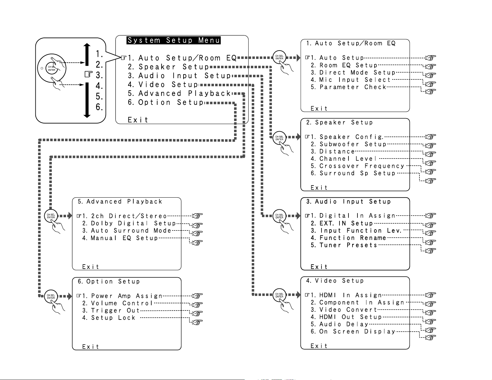
2 System setup menu
page 75
page 76
page 76, 77
page 77, 78
page 78, 79
page 79
page 63
page 63, 64
page 64
page 64
page 65, 66
page 66, 67
page 67
page 67
page 67, 68
page 68
page 69
page 70
page 70
page 70, 71
page 72
page 72, 73
page 73, 74
page 74
page 9~13
page 80
page 80
page 80
page 81
page 68, 69

2
We greatly appreciate your purchase of the AVR-3806.
2
To be sure you take maximum advantage of all the features the AVR-3806 has to offer, read
these instructions carefully and use the set properly. Be sure to keep this manual for future
reference should any questions or problems arise.
“SERIAL NO.
PLEASE RECORD UNIT SERIAL NUMBER ATTACHED TO THE REAR OF THE CABINET FOR
FUTURE REFERENCE”
MEMO

2
Getting Started Getting Started
Accessories
Check that the following parts are included in addition to the main unit:
q Operating instructions ……………………….1
w Warranty (for North America model only)…1
e Service station list …………………………….1
r Power supply cord …………………………….1
t Remote control unit (RC-1024) ……………1
y LR6/AA alkaline batteries……………………2
u AM loop antenna ………………………………1
i FM indoor antenna ……………………………1
o Setup microphone (DM-S205) …………….1
Before using
Pay attention to the following before using this
unit:
• Moving the unit
To prevent short-circuits or damaged wires in
the connection cables, always unplug the power
supply cord and disconnect the connection
cables between all other audio components
when moving the unit.
• Before turning the power switch on
Check once again that all connections are
correct and that there are not problems with
the connection cables. Always set the power
switch to the standby position before
connecting and disconnecting connection
cables.
• Store these instructions in a safe place.
After reading, store this instructions along with
the warranty card in a safe place.
• Note that the illustrations in these
instructions may differ from the actual unit
for explanation purposes.
Advanced Setup – Part 1
Navigating through the System Setup Menu····················61
On screen display and front display ···································62
Audio Input Setup
Setting the Digital In Assignment·········································63
Setting the DENON LINK ·····················································63
Setting the EXT. IN Setup···············································63, 64
Setting the Input Function Level ··········································64
Setting the Function Rename···············································64
Tuner Presets ·································································65, 66
Video Setup
Setting the HDMI In Assign ···········································66, 67
Setting the Component In Assign ········································67
Setting the Video Convert ····················································67
Setting the HDMI Out Setup··········································67, 68
Setting the Audio Delay························································68
Setting the On Screen Display (OSD) ····························68, 69
Advanced Playback
Setting the 2ch Direct / Stereo·············································69
Setting the Dolby Digital Setup ············································70
Setting the Auto Surround Mode ·········································70
Setting the Manual EQ Setup ········································70, 71
Procedure for copying the “Flat” correction curve ··············71
Option setup
Setting the Power Amplifier Assignment·····························72
Setting the Volume Control············································72, 73
Setting the Trigger Out ···················································73, 74
Setup Lock············································································74
Advanced Setup – Part 2
Speaker Setup
Setting the type of speakers ················································75
Setting the low frequency distribution ·································76
Setting the Distance·······················································76, 77
Setting the Channel Level ··············································77, 78
Setting the Crossover Frequency·········································78
Setting the crossover frequency individually
for the different channels ·····················································79
Selecting the surround speakers for the
different surround modes·····················································79
Others Setup
Setting the Room EQ Setup·················································80
Setting the Direct Mode Setup ············································80
Setting the MIC Input Select················································80
Check the parameter····························································81
System setup items and default values·······················82~84
Troubleshooting ······························································85, 86
Additional Information···················································87
~99
Specifications ······································································100
List of preset codes ····································End of this manual

3
Getting Started Getting Started
Cautions on handling
• Switching the input source when input terminals are not connected.
A clicking noise may be produced if the input source is switched when nothing is connected to
the input terminals. If this happens, either turn down the MASTER VOLUME control knob or
connect components to the input terminals.
• Muting of PRE OUT terminals, PHONES jack and SPEAKER terminals.
The PRE OUT terminals, PHONES jack and SPEAKER terminals include a muting circuit. Because
of this, the output signals are greatly attenuated for several seconds after the power switch is
turned on or the input source, surround mode or any other set-up is changed. If the volume is
turned up during this time, the output will be very high after the muting circuit stops functioning.
Always wait until the muting circuit turns off before adjusting the volume.
• Whenever the power switch is in the STANDBY state, the unit is still connected to AC line
voltage.
Please be sure to turn off the power switch or unplug the cord when you leave home for,
say, a vacation.
Preparing the remote control unit
The included remote control unit (RC-1024) can be used to operate not only the AVR-3806 but other
remote control compatible DENON components as well. In addition, the memory contains the
control signals for other remote control units, so it can be used to operate non-DENON remote
control compatible products.
Cautions on installation
Noise or disturbance of the picture may be
generated if this unit or any other electronic
equipment using microprocessors is used near
a tuner or TV.
If this happens, take the following steps:
• Install this unit as far away as possible
from the tuner or TV.
• Run the antenna wires from the tuner or
TV away from this unit’s power supply cord
and input/output connection cables.
• Noise or disturbance tends to occur
particularly when using indoor antennas or
300 Ω/ohms feeder wires. We
recommend using outdoor antennas
and 75 Ω/ohm coaxial cables.
Wall
Note
Note:
For heat dispersal, do not install this unit in a confined space such as a bookcase or similar
enclosure.
Operating range of the remote control unit
30°
30°
Approx. 23 feet/7 m
• Point the remote control unit at the remote sensor on the main unit as shown in the diagram.
• The remote control unit can be used from a straight distance of approximately 23 feet/7 meters
from the main unit, but this distance will be shorter if there are obstacles in the way or if the
remote control unit is not pointed directly at the remote sensor.
• The remote control unit can be operated at a horizontal angle of up to 30 degrees with respect
to the remote sensor.
NOTE:
• It may be difficult to operate the remote control
unit if the remote sensor is exposed to direct
sunlight or strong artificial light.
• Do not press buttons on the main unit and
remote control unit simultaneously. Doing so
may result in malfunction.
• Neon signs or other devices emitting pulsetype noise nearby may result in malfunction,
so keep the set as far away from such devices
as possible.
Inserting the batteries
q Remove the remote control unit’s rear
cover.
w Set two LR6/AA batteries in the battery
compartment in the indicated direction.
e Put the rear cover back on.
Notes on batteries:
• Replace the batteries with new ones if the set
does not operate even when the remote
control unit is operated nearby the unit. (The
included batteries are only for verifying
operation.)
• When inserting the batteries, be sure to do so
in the proper direction, following the “<” and
“>” marks in the battery compartment.
• To prevent damage or leakage of battery fluid:
• Do not use a new battery together with an
old one.
• Do not use two different types of batteries.
• Do not short-circuit, disassemble, heat or
dispose of batteries in flames.
• If the battery fluid should leak, carefully wipe
the fluid off the inside of the battery
compartment and insert new batteries.
• When replacing the batteries, have the new
batteries ready and insert them as quickly as
possible.

4
Display
Getting Started Getting Started
q
Input signal indicator
The respective indicator will light corresponding
to the input signal.
w
Input signal channel indicator
The channels included in the input source
will light.
This lights when the digital signal is inputted.
e
Information display
This displays the surround mode, function
name or setting value, etc.
r
Output signal channel indicator
The audio channels that can be output light.
t
Speaker indicator
This lights corresponding to the settings of
the surround speakers of the various
surround modes.
y
Master volume indicator
This displays the volume level.
The Setup item number is displayed in
System Setup.
u
Multi (zone) indicator
ZONE2 mode is selected in ZONE2/REC
SELECT.
i
Recording output source indicator
REC OUT mode is selected in ZONE2/REC
SELECT.
o
DENON LINK indicator
This lights during playback in a DENON LINK
connection.
!0
AL24 indicator
The AL24 indicator lights when the PURE
DIRECT, DIRECT, STEREO, MULTI CH PURE
DIRECT, MULTI CH DIRECT, MULTI CH IN
mode is selected in the PCM input signal.
!1
Input mode indicator
This lights corresponding to the setting of
the input mode.
!2
AUTO indicator
This lights when the broadcast station is
selected in the AUTO tuning mode.
!3
TUNED indicator
This lights when an FM/AM broadcast has
been received.
!4
STEREO indicator
This lights when an FM stereo broadcast has
been received.
Part names and functions
Front panel
For details on the functions of these parts, refer to the pages given in parentheses ( ).
#7#7
#6#6
#5#5
#4#4
#3#3 #2#2
#1#1
#0#0
@9@9
@8@8
@7@7
!4 !2 !1 !0!3@0
#7
#6
!9
#5#4#3 #2#1#0@9@8
@7
q w e r
t
u i o
@1
@2@3@4 @6
@5
#8
y
!5
!8
!7
!6
q
Power ON/STANDBY switch··············(10)
w
Power indicator····································(10)
e
Power switch ·································(10, 60)
r
Headphones jack (PHONES) ···············(28)
t
V.AUX INPUT terminals ······················(17)
y
SETUP MIC jack ···································(10)
u
USER MODE 1 button ·························(38)
i
USER MODE 2 button ·························(38)
o
USER MODE 3 button ·························(38)
!0
Master volume control knob ··············(27)
!1
Master volume indicator·····················(27)
!2
Display
!3
Remote control sensor··························(3)
!4
FUNCTION knob···································(27)
!5
SOURCE button ···································(27)
!6
TUNING PRESET button ·····················(44)
!7
ZONE2/3/REC SELECT button······(58, 60)
!8
VIDEO SELECT button·························(28)
!9
MultEQ XT indicator····························(30)
@0
NIGHT indicator ···································(34)
@1
INPUT MODE button ···························(28)
@2
ANALOG button···································(30)
@3
EXT. IN button ······································(28)
@4
SYSTEM SETUP button ······················(11)
@5
CURSOR button ···································(11)
@6
SURROUND BACK button ··················(33)
@7
ROOM EQ button·································(30)
@8
STATUS button ····································(29)
@9
DIMMER button ···································(29)
#0
TONE DEFEAT button··························(42)
#1
SURROUND PARAMETER button ······(33)
#2
CH SELECT/ENTER button ·················(42)
#3
DSP SIMULATION button ···················(40)
#4
7CH STEREO button ····························(40)
#5
STANDARD button ······························(27)
#6
DIRECT/STEREO button······················(32)
#7 PURE DIRECT button ···························(32)
#8 NIGHT button ·······································(34)

5
Getting Started Getting Started
Remote control unit
Surround mode/System
buttons·················(27, 47)
Mode selector buttons
····································(47)
IR segment
····································(49)
ROOM EQ button
····································(30)
SYSTEM SETUP button
····································(11)
Cursor buttons
····································(10)
SURROUND
PARAMETER/SEARCH
button···················(33, 46)
Tuner system buttons
····································(43)
Mode selector button
····································(47)
Remote control signal
transmitter···················(3)
Input mode selector
buttons·······················(28)
NIGHT button
····································(34)
SPEAKER button
····································(28)
TEST TONE button
····································(78)
Tuner system buttons
····································(43)
CH SELECT/ENTER
button
····························
(42)
Power buttons
····································(10)
Master volume control
buttons·······················(27)
ON SCREEN button
····································(29)
Function/Number
buttons·······················(27)
Muting button
····································(28)
User mode/System
call button············(38, 53)
VIDEO SELECT button
····································(28)
• With the AVR-3806, the “AUX” button cannot be used.
• For instructions on setting the remote control unit back light’s lighting time ( page 54).
MEMO
For details on the functions of these parts, refer to the pages given in parentheses ( ).
Rear panel
q
Digital audio terminals (Optical/Coaxial) ···(8)
w
Analog audio terminals·························(8)
e
Pre-out terminals ·································(25)
r
Speaker terminals··································(7)
t
AC outlet (s) ·········································(25)
y
AC inlet ·················································(25)
u
Component video terminals ·················(8)
i
Video/S-Video terminals·······················(8)
o
12V TRIGGER OUT terminals ·············(23)
!0
Remote control terminals ···················(24)
!1
RS-232C terminal ·································(23)
!2
EXT. IN terminals ·································(17)
!3
AM/FM antenna terminals··················(22)
!4
HDMI terminals ····································(20)
!5
DENON LINK terminal ·························(20)
!6
XM terminal ········································(23)
!3
u!1!2!4 io!0
y
!5
!6
q
w r t
e

6
Easy Setup and Operation
Speaker system layout
2 Basic system layout
The following is an example of the basic layout for a system consisting of eight speaker systems
and a television monitor:
Subwoofer Center speaker system
Surround speaker systems
Surround back speaker systems
Front speaker systems
Set these at the sides of the TV
or screen with their front surfaces
as flush with the front of the
screen as possible.
With the AVR-3806 it is also possible to use the surround speaker selector function to choose the
best layout for a variety of sources and surround modes.
2 Surround speaker selector function
This function makes it possible to achieve the optimum sound fields for different sources by
switching between two systems of surround speakers (A and B). The settings of the different
speakers (A only, B only or A+B) are stored in the memory for the different surround modes, so
they are set automatically when the surround mode is selected.
Using A only
(Multi surround speaker system)
Using B only
(Single surround speaker system)
( SB: Surround back speakers)
• This section contains the basic steps necessary to configure the AVR-3806 according to your
listening room environment and the source equipment and loudspeakers you are using.
• For optimum performance, we recommend using the Auto Setup function.
• If you wish, you can set the various settings manually without using Auto Setup ( page 75 ~
79).
Easy to setup flow
Easy Setup and Operation
Placing the speakers.
Connecting the
speakers.
Connecting a monitor
and a DVD player.
Starting the Auto
Setup.
Playing a DVD with
surround sound.
Auto setup flow
1) Speaker Configuration
2) Distance
3) Channel Level
4) Crossover Frequency
5) Room EQ
1) Measuring the background noise (noise in the
room)
2) Determining whether or not speakers are
connected
3) Checking the polarities of the speakers
Store the measurement result in the memory.
Connecting a microphone.
Preliminary measurement
Measurement of the speakers
in the listening position.
Check of the measurement result.
The measurement of the speakers
in the 2nd to 6th listening position

7
Easy Setup and Operation Easy Setup and Operation
2 Connections
• The AVR-3806 can be configured for 10 speaker playback using two pairs of surround speakers
(A+B) and one pair of surround back speakers as shown below.
• The output of the surround back’s power amplifier can be assigned to the multi zone or front
channel.
For details, refer to “Setting the Power Amplifier Assignment” (page 72).
• When making connections, also refer to the operating instructions of the other components.
Precautions when connecting speakers:
If a speaker is placed near a TV or video
monitor, the colors on the screen may be
disturbed by the speaker’s magnetism. If
this should happen, move the speaker away
to a position where it does not cause this
effect.
NOTE:
• When using only one surround back
speaker, connect it to the left channel.
><
><
><
><><><><
><
><
IN
(R) (L) (L) (R)
(L)
(R)
(L)
(R)
Connection
terminal for
subwoofer
with built-in
amplifier
(subwoofer),
etc.
Speaker connections
• Connect the speaker terminals with the
speakers making sure that like polarities are
matched (<with <, >with >). Mismatching
of polarities will result in weak central sound,
unclear orientation of the various instruments,
and the stereo image being impaired.
• When making connections, take care that
none of the individual conductors of the speaker
cable come in contact with adjacent terminals,
with other speaker cable conductors, or with
the rear panel.
2 Speaker impedance
• Speakers with an impedance of from 6 to 16
Ω/ohms can be connected for use as front,
center, surround and surround back speakers.
• Be careful when using two pairs of surround
speakers (A + B) at the same time, since use
of speakers with an impedance of less than 8
Ω/ohms will lead to damage.
• The protector circuit may be activated if the
set is played for long periods of time at high
volumes when speakers with an impedance
lower than the specified impedance are
connected.
Protector circuit
This unit is equipped with a high-speed
protection circuit. The purpose of this circuit
is to protect the speakers under circumstances
such as when the output of the power
amplifier is inadvertently short-circuited and
a large current flows, when the temperature
surrounding the unit becomes unusually
high, or when the unit is used at high output
over a long period which results in an
extreme temperature rise.
When the protection circuit is activated, the
speaker output is cut off and the power
supply indicator flashes. Should this occur,
please follow these steps: be sure to switch
off the power of this unit, check whether
there are any faults with the wiring of the
speaker cables or input cables, and wait for
the unit to cool down if it is very hot.
Improve the ventilation condition around the
unit and switch the power back on.
If the protection circuit is activated again
even though there are no problems with the
wiring or the ventilation around the unit,
switch off the power and contact a DENON
service center.
Note on speaker impedance
The protector circuit may be activated if the
set is played for long periods of time at high
volumes when speakers with an impedance
lower than the specified impedance (for
example speakers with an impedance of
lower than 4 Ω/ohms) are connected. If the
protector circuit is activated, the speaker
output is cut off. Turn off the set’s power,
wait for the set to cool down, improve the
ventilation around the set, then turn the
power back on.
NOTE:
NEVER touch the speaker terminals
when the power is on. Doing so could
result in electric shocks.
Connecting the speaker cables
1. Loosen by turning
counterclockwise.
Either tightly twist or
terminate the core wires.
2. Insert the cable.
3. Tighten by turning
clockwise.
Connecting banana plugs
Turn clockwise to
tighten, then insert
the banana plug.
Surround
speaker
Systems (B)
Front speaker
Systems
Surround
speaker
Systems (A)
Subwoofer
Surround back
speaker
Systems
Center
speaker
8
Easy Setup and Operation Easy Setup and Operation
Monitor TV
S VIDEO
IN
VIDEO
IN
COMPONENT VIDEO IN
Y
P
B
PR
HDMI
IN
G
I
H
J
For best picture quality (especially with progressive DVD and other high definition sources), choose
the component video or HDMI connection to your monitor TV. S-Video and composite video
outputs are also provided if your TV does not have component video inputs.
NOTE:
• The component video input and/or output jacks may be labelled differently on some TVs,
monitors or video components (Y, P
B, PR; Y, CB, CR; Y, B-Y, R-Y). Check the owner’s manuals
for other components for further information.
• The COMPONENT MONITOR OUT-1 and the COMPONENT MONITOR OUT-2 can be used
simultaneously.
• Audio signals are only output from the HDMI monitor out terminal when audio signals are
input to the HDMI input terminal.
• When connecting the AVR-3806 and DVD player using an HDMI cable, also connect the AVR3806 and monitor TV using an HDMI cable ( page 20).
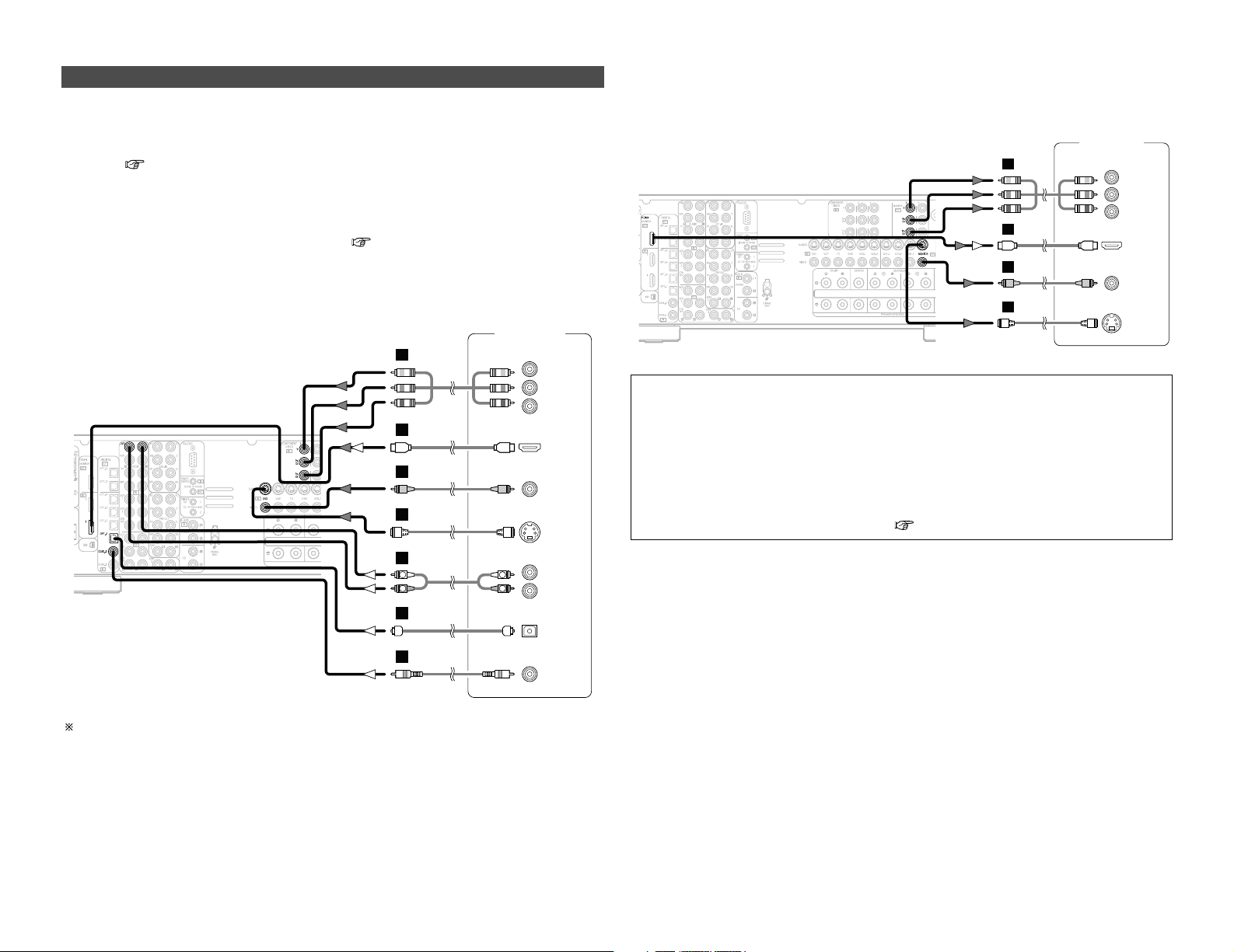
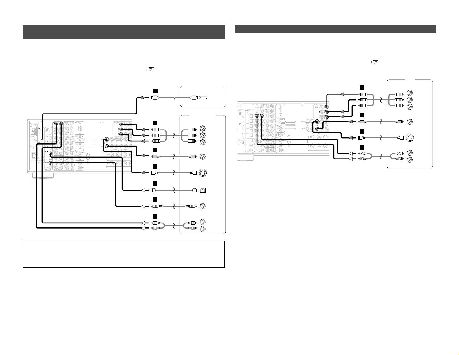
Connecting a DVD player and monitor TV
• To connect the video output from the DVD player to the AVR-3806, you only need to choose one
connection type. Component video connection offers the best quality (and is required for
progressive DVD playback), followed by S-Video, while composite video offers the lowest picture
quality of the three connection types. For more information about the video up conversion
function ( page 15).
• The AVR-3806 is equipped with HDMI connectors, so it can be connected to a DVD player or
monitor TV using an HDMI cable.
• To connect the digital audio output from the DVD player, you can choose from either the coaxial
or optical connections. If you choose to use the optical connection, it needs to be assigned. For
more information about Digital Input Assignment ( page 63).
• The AVR-3806 is equipped with another set of input terminals for a non-DVD Video Disc Player
(such as laser disc, VCD/SVCD, or future high definition disc player). The above connection
guidelines for DVD also apply to the VDP input.
Audio signal flow is shown with white arrows; video signal flow is shown with gray arrows.
DVD player
S VIDEO
OUT
COAXIAL
OUT
R
L
AUDIO OUT
VIDEO
OUT
COMPONENT VIDEO OUT
Y
P
B
PR
OPTICAL
OUT
HDMI
OUT
R
L
R
L
G
I
H
A
C
D
J

9
Easy Setup and Operation Easy Setup and Operation
Auto Setup / Room EQ
The Auto Setup and Room EQ function of this
unit performs an analysis of the speaker system
and measures the acoustic characteristics of your
room to permit an appropriate automatic setting.
The AVR-3806’s Audyssey MultEQ XT function
has the feature that it provides the optimum
listening environment at all listening positions in
the home theater, where there are often
multiple listeners viewing programs together.
To achieve this, it is first necessary to use a
microphone to measure test tones generated
from the different speakers at the various
listening positions. All this measured data is
analyzed with a unique method to
comprehensively improve acoustic characteristics
in the listening area. For optimum effectiveness,
measurements should be performed at six
points. Move the microphone successively
within the listening area surrounded by the
speakers as shown on the diagram below to
measure the test tones. When listening to
music or viewing movies with the whole family,
move the microphone successively to the
different positions in which the members of the
family sit (“ ” on the diagram indicates the
points of installation) and measure repeatedly
(Example q). Even if the number of people
using the home theater is small, taking multiple
measurements at or near the listening positions
makes it possible to correct the sound more
effectively (Example w).
The AVR-3806’s Room EQ function offers three
correction curves: “Audyssey”, “Front” and
“Flat”. These can be selected after performing
the auto setup procedure. Details of the
different correction curves are described below.
• Audyssey:
This adjusts the frequency response of all
speakers to correct the effects of room
acoustics.
• Front:
This adjusts the characteristics of each
speaker to the characteristics of the front
speakers.
• Flat:
This the frequency response of all speakers flat.
This is suitable for multi-channel music
reproduction, from discrete music sources
such as Dolby Digital 5.1, DTS, DVD-Audio
and Super Audio CD.
2 About the main listening position
(*M)
The main listening position is the point where a
listener sits most often or the listening position
when only one person is listening.
Measurements on the AVR-3806 start from this
point. Correction for the speaker distance is set
based on this point.
Example:
w
• To make the Speaker system settings without
using the Auto Setup function ( page 75 ~
79).

10
Easy Setup and Operation Easy Setup and Operation
Connecting a microphone
1
Connect the microphone for Auto Setup to the
SETUP MIC jack on the front panel of the unit.
2
Mount the auto setup microphone onto a camera
tripod, etc., and place it at ear height at the main
listening position in the listening room with the
sound receptor facing the ceiling.
Microphone
NOTE:
• Do not disconnect the microphone until the settings are
completed.
• Do not change the connection of speakers or the
subwoofer’s volume after performing these measurements.
When placing the microphone, adjust the height so that the
microphone’s sound receptor is at the height of the ears of
the listener.
Be sure that at the beginning, the measurement is started
with the microphone set up at the main listening position.
It is not possible to measure properly if there are any
obstacles between the speakers and microphone. Check
that there are no obstacles.
Please do not stand between or near the speakers and the
microphone during the measurements.
ENTER
ON
OFF
CURSOR
SYSTEM
SETUP
AMP
ON/STANDBY
SYSTEM SETUP
CURSOR
POWER ENTER SETUP MIC
4
Press the ON/STANDBY switch on the main unit
or ON button on the remote control unit.
• When pressed, the power turns on and the display lights.
• When pressed again, the power turns off, the standby
mode is set and the display turns off.
3
Press the POWER switch.
£ OFF:
The power turns off and the indicator is off.
In this position, the power cannot be turned on and off from
the remote control unit.
¢ ON:
The power turns on and the indicator lights.
Set the POWER switch to this position to turn the power on
and off from the included remote control unit.
1
Turn on your subwoofer.
Turn on your monitor (TV).
Turning on the power
5
Press the AMP button to select the “AMP” mode
(only when operating with the remote control
unit ( page 26)).
2
The sound is muted for several seconds, after which the
unit operates normally.
When ever the ON/STANDBY button is in the standby state,
the apparatus is still connected to the AC line voltage.
Please be sure to turn off the POWER switch or unplug the
cord when you leave home for, say, a vacation.
Set the volume to halfway and set the crossover frequency
to the maximum or Low pass filter off if your subwoofer can
adjust the output volume and the crossover frequency
Some subwoofers have a standby mode. Be sure to turn
this function off before performing the Auto Setup
procedure.
11
Easy Setup and Operation Easy Setup and Operation
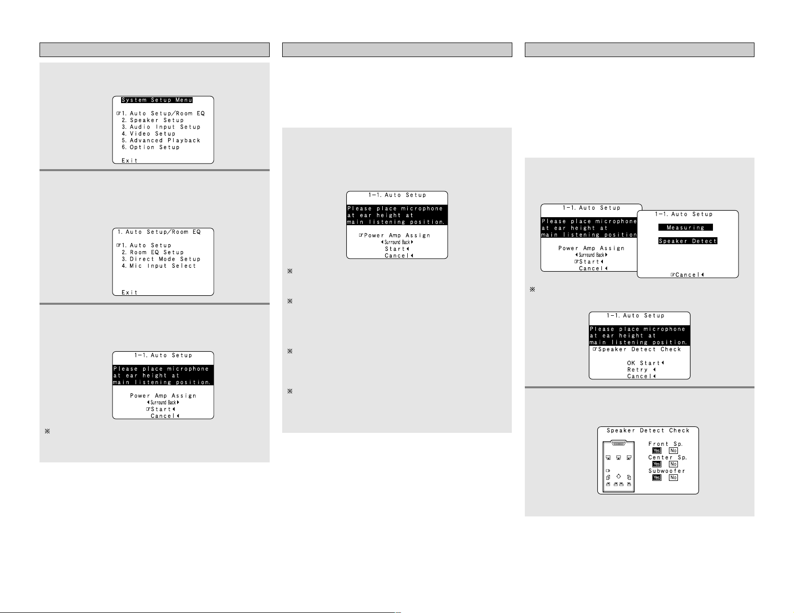
Starting Auto Setup Power Amp Assign
2
Press the CURSORDDorHHbutton to select the
“Auto Setup / Room EQ”, then press the ENTER
button.
• The “Auto Setup / Room EQ” menu screen appears.
Press the CURSOR
DD
orHHbutton to select the
“Power Amp Assign”, then press the CURSORFFor
GG
button to select the “Surround Back”, “Front”,
“Front B”, “ZONE2” or “ZONE3”.
1
Press the SETUP button.
• The “System Setup Menu” appears.
The AVR-3806 has available surround back amplifier channel. If
no surround back speakers are used in the main room, their
amplifier channels can be assigned for multi-zone use or the front
speaker‘s Bi-Amp connection. If this functionality is not needed,
skip this “Power Amp Assign” procedure and proceed to
“Preliminary Measurements”.
The message “Connect Microphone” is displayed if no
microphone is connected. If so, connect the auto setup
microphone.
3
Press the CURSORDDorHHbutton to select the
“Auto Setup”, then press the ENTER button.
• The “Auto Setup” screen appears.
When “Surround Back” is selected, the surround back
channel‘s test tone during Auto Setup will be output from
surround back speakers.
When “Front” is selected, change the setting to a Bi-Amp
mode for the front speakers.
The front channel‘s test tone during Auto Setup will be
output from the front speakers and the surround back
speakers.
When “Front B” is selected, change the setting to a second
stereo output mode.
The test tone during Auto Setup will not be output from the
surround back speakers.
When “ZONE2” or “ZONE3” is selected, change the
setting to “ZONE2” or “ZONE3”.
The test tone during Auto Setup it will not be output to
“ZONE2” or “ZONE3” (Another room).
Preliminary measurements
• This procedure is used to automatically determine the
background noise, whether or not speakers are connected, and
the polarities of the connected speakers.
• To avoid affecting the measurements, turn off the airconditioner or any other device that makes noise and take the
measurements with the room as quiet as possible.
• The set measures the background noise even when in the
silent state with no test tones being output, so keep as quiet as
possible until the measurements are completed.
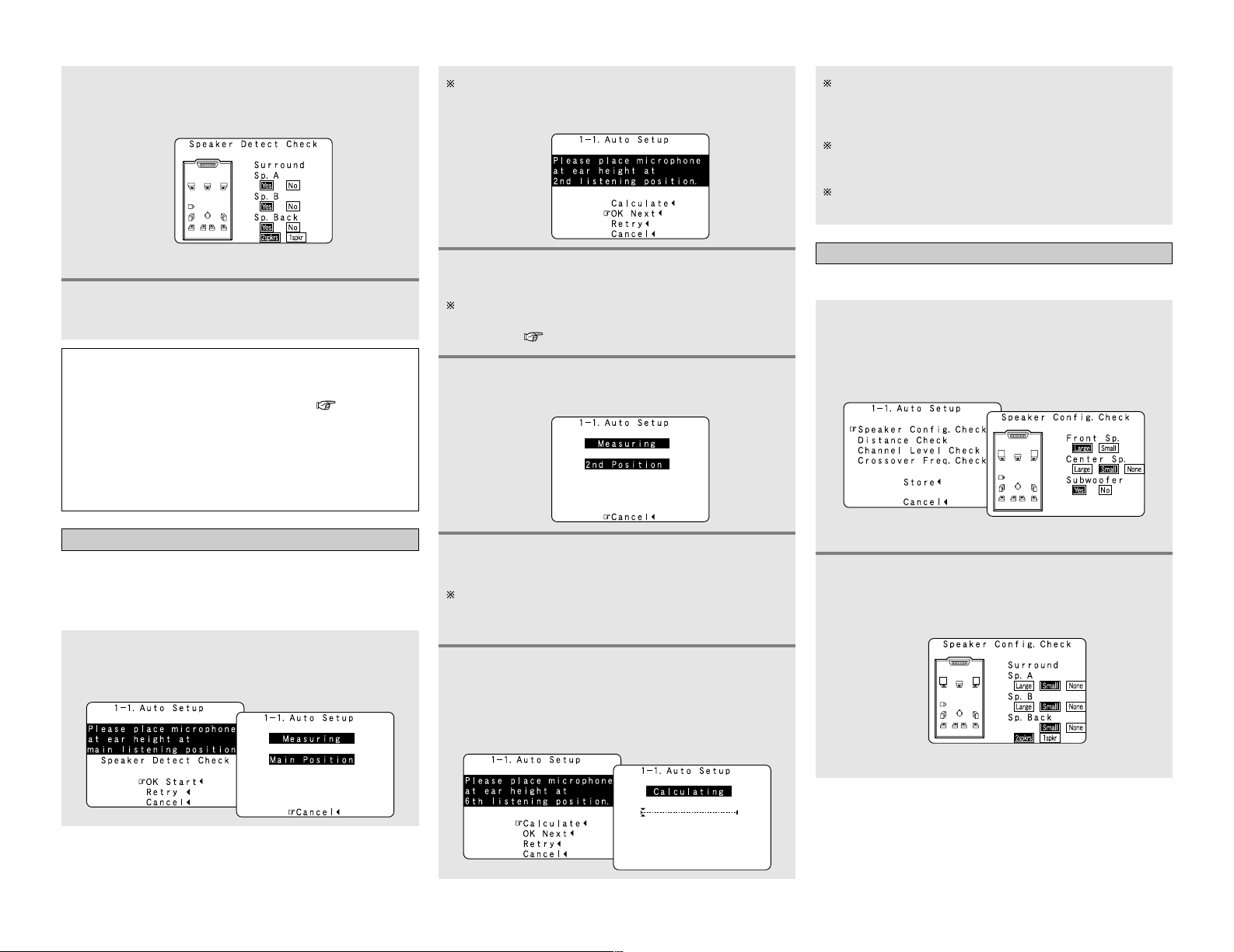
2
Press the ENTER button.
•The “Speaker Detect Check” screen appears.
[ First screen ]
1
Press the CURSORDDorHHbutton to select the
“Start”, then press the CURSOR FFbutton.
• The preliminary measurements start.
The screen shown at the below appears once the
preliminary measurements are completed.
Easy Setup and Operation Easy Setup and Operation
12
Speaker system measurement
1
Press the CURSORDDorHHbutton to select the
“OK Start”, then press the CURSOR
FF
button.
• Measurements for the first point start.
The screen shown at the below appears once the
measurements for the main listening position are
completed.
3
Check the results of the speaker detection, then
press the ENTER button.
• The second screen appears.
[ Second screen ]
4
If the check ends, press the ENTER button again.
NOTE:
• If the results are not as expected or if an error message is
displayed, select “Retry” and perform the measurements
again. (For details on the error messages ( page 13).
If the results of remeasurement are still not as expected or
if an error message is displayed, turn off the power switch
and check the speaker connections. Then start the
measurements again from the beginning.
• Measurement is cancelled when MASTER VOLUME is
operated while the Auto Setup is performed.
With these measurements, the “Speaker Configuration”,
“Distance”, “Channel Level”, “Crossover Frequency” and
“Room EQ” are analyzed automatically. The main listening
position is measured first, so leave the microphone where it is.
4
Perform step 2, 3 repeatedly.
5
After measuring at the number of points
according to your listening environment, press
the CURSOR
DD
or
HH
button to select the
“Calculate”, then press the CURSOR
FF
button.
• The speaker system is analyzed.
The more measurement points, the better the resulting room
correction effect. We recommend 6 measurement points – 6
measurement points provides the best room correction effect.
2
Next the measurements for the second point will
be taken.
3
Press the CURSOR
FF
button.
• Measurements for the second point start.
Place the microphone at the second listening position. For
instructions on the position in which the microphone should
be placed ( page 9).
The amount of time required for the analysis depends on the
number of speakers and the number of measuring points.
The greater the number of speakers and measuring points,
the longer the time required.
Measurements can be ended when there are 6 or less
measurement locations; however, to obtain better results,
measurements at 6 locations is recommended.
Once the calculations are completed, a screen for
confirming the results of the measurements appears.
Check of the measurement result
1
Press the CURSORDDorHHbutton to select an
item, then press the ENTER button.
• The verification screen appears.
Example: Speaker Config. Check
2
Press the ENTER button.
• The second screen appears.
Example: Speaker Config. Check
The results of the measured items can be checked.
[ First screen ]
[ Second screen ]

13
Easy Setup and Operation Easy Setup and Operation
Store:
Store the checked measurement values.
All parameters are stored.
3
If the check ends, press the ENTER button again.
4
Press the CURSOR
DD
orHHbutton to select
whether or not to save the data you have
checked.
5
Press the CURSORFFbutton.
• After the data is stored, the “Auto Setup / Room EQ”
menu screen appears automatically.
Cancel:
Cancel the auto setup settings.
• When measurements have been made using the measurement
microphone, speakers with a built-in filter such as subwoofers
might be set with a value that differs from the physical distance
because of the internal electrical delay.
NOTE:
• Do not turn off the power while the data is being stored.
If the power is turned off while the data is being stored, the
Room EQ parameters stored in the memory will be cleared,
and it will not be possible to select the “Audyssey”, “Front”
or “Flat” equalizer settings.
Measures
Cause
Screen example
q The speakers required for producing suitable
reproduction have not been detected.
• The front L and front R speakers were not properly
detected.
• Only one channel of the surround (A) and surround (B)
speakers was detected.
• Sound was output from the R channel when only one
surround back speaker was connected.
• The surround back or the surround (B) speaker was
detected, but the surround (A) speaker was not
detected.
If multiple errors occur, press the CURSORFFor GGbutton
to check the contents.
• Check that the pertinent speakers are properly
connected.
w The speaker polarity is connected in reverse.
If multiple errors occur, press the CURSORFFor GGbutton
to check the contents.
• Check the polarity of the pertinent speakers.
• For some speakers, the screen below may be
displayed even though the speakers are
properly connected.
If so, select “Skip
0
”.
e There is too much ambient noise in the room and the
measurements cannot be made accurately.
r The sound level that is output from the speakers and/or
subwoofer is too low.
• Either turn off the power of the device that
generated the noise during the measurements
or move the device away.
• Try again at a time when it is quieter.
• Check the placement and orientation of the
loudspeakers.
• Adjust the subwoofer’s output level.
t The measurement microphone is not connected, or all
of speakers have not been detected.
• Connect the measurement microphone to the
microphone connector.
• Check the speaker connection.
Playing a DVD with surround sound
1
Disconnect the microphone from the unit.
2
Select the input source to be played.
4
5
Adjust the volume.
Start DVD playback.
About the error message
These error messages will be displayed when performing the measurements of Auto Setup and the automatic measurements can
not be completed because of the speaker arrangement, measurement environment, or other factors. Please check the following
matters, reset the pertinent items, and measure again. Be sure to turn off the AVR-3806’s power before checking the speaker
connections.
3
Select the play (surround) mode.
14
Connecting Other Sources
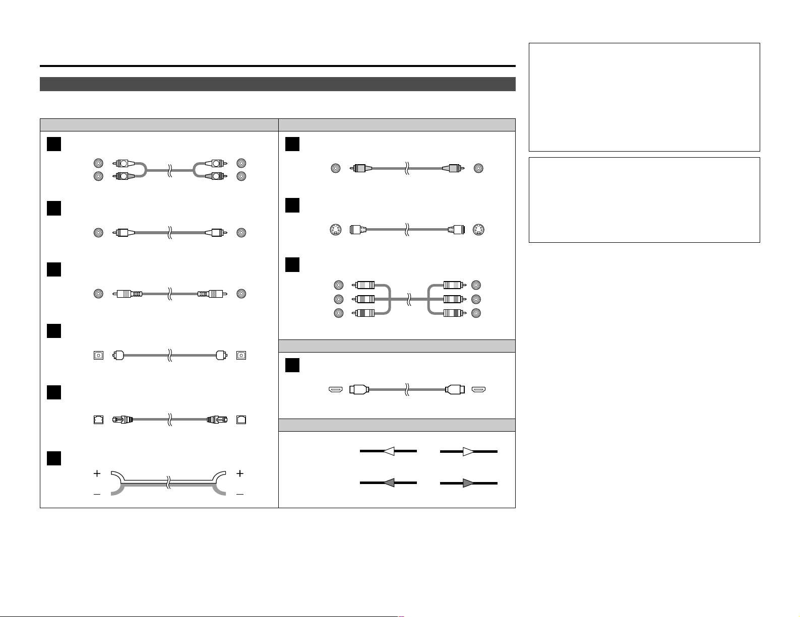
Cable indications
Signal direction
Audio and Video cable
The hookup diagrams on the subsequent pages assume the use of the following optional connection cables (not supplied).
Video cableAudio cable
NOTE:
• Do not plug in the power supply cord until all connections
have been completed.
• When making connections, also refer to the operating
instructions of the other components.
• Be sure to connect the left and right channels properly (left
with left, right with right).
• Note that binding pin-plug cables together with power
supply cords or placing them near a power transformer will
result in hum or other noise.
NOTE:
• Connecting a LD (laser disc) player with a Dolby Digital
RF Output.
The AVR-3806 does not have a DD RF demodulator function.
Therefore, you need to use a commercially available
outboard DD RF demodulator and connect its digital output
to one of the AVR-3806 available digital inputs. Refer to the
demodulator’s owner’s manual for further information.
Analog terminal (Stereo)
A
(Orange)
Pin-plug cable
Analog terminal (Monaural, for subwoofer)
B
Pin-plug cable
Digital terminal (Coaxial)
C
Coaxial cable (75 Ω/ohm pin-plug cable)
(Yellow)
Digital terminal (Optical)
D
Optical cable (Optical fiber cable)
DENON LINK terminal
E
DENON LINK cable
Speaker terminal
F
Speaker cable
Video terminal
G
HDMI terminal
J
HDMI cable
Video cable (75 Ω/ohms video pin-plug cable)
S-Video terminal
H
S-Video cable
Audio signal
Video signal
(White)
(Red)
Component video terminal
I
Component video cable
(Y)
(PB/CB)
(P
R/CR)
(Green)
(Blue)
(Red)
IN OUT OUT IN
IN OUT OUT IN
Connecting Other Sources
15
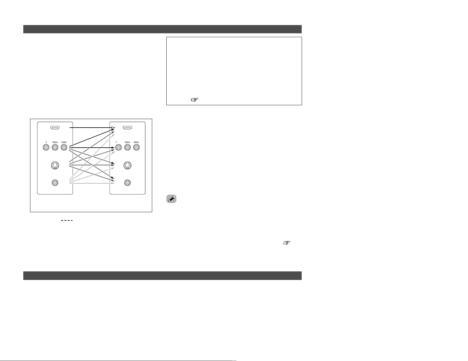
Connecting Other Sources Connecting Other Sources
The AVR-3806 is equipped with a function for up and down
converting video signals.
Because of this, the AVR-3806’s MONITOR OUT terminal can be
connected to the monitor (TV) with a set of cables offering a
higher quality connection, regardless of how the player and the
AVR-3806’s video input terminals are connected.
Generally speaking, analog video connections using the
component video terminals offer the highest quality playback,
followed by connections using the S-Video terminals, then
connections using the regular video terminals (yellow).
The flow of the video signals.
This unit’s input
terminals
This unit’s output
terminals
: only MAIN ZONE 480i/576i
(Component Video
terminals)
(Component Video
terminals)
(S-Video terminal)
(Video terminal)
The video conversion function
On screen display for component video outputs and HDMI output
(HDMI terminal)
(HDMI
terminal)
(S-Video terminal)
(Video terminal)
NOTE:
• It is not possible to down-convert from HDMI input signals
to the component, S-Video or composite video monitor
output terminals.
• Video down conversion to the MAIN ZONE’s monitor output
is only possible when the component video input resolution
is 480i (interlaced standard definition video – NTSC format,
for North America) or 576i (interlaced standard definition
video – PAL format, for Europe and other countries).
• To set the video conversion function for the MAIN ZONE to
“OFF” ( page 67).
2 The analog video to HDMI conversion function:
• The AVR-3806’s video up-conversion function lets you output
analog video input signals (component – 480i/576i, 480p/576p,
1080i or 720p; S-Video and composite video — 480i/576i) to the
HDMI monitor output terminal with the original resolution.
• The on screen display signals are output from the HDMI
monitor output terminal with a resolution of 480i/576i. Because
of this, if the monitor equipped with HDMI terminal is
compatible with the 480i/576i resolution, all the signals the
AVR-3806 handles can be output to the monitor with a single
HDMI cable. The resolutions with which the monitor is
compatible can be checked using the STATUS button on the
main unit or the ON SCREEN button on the remote control unit.
• If the monitor equipped with HDMI terminal is not compatible
with the 480i/576i resolution, connect the player and the AVR3806 using a component cable and set the player’s resolution
to one which the monitor can handle.
• If you do not want to use the function for converting analog
video signals to HDMI signals, select “OFF” for “Analog to
HDMI Convert” at “Setting the HDMI Out Setup”( page
67).
In this case, the function for video up conversion to the
component video terminal operates.
• When viewing component video signals or HDMI signals via the AVR-3806, the on screen display is displayed on the monitor when
the “System Setup” operations are performed and when the remote control unit’s ON SCREEN button is operated.
• To view the on screen display using an HDMI monitor, set “Analog to HDMI Convert” at “HDMI Out Setup” to “ON” (default).
• When only component video signals are input to the AVR-3806, the characters of the on screen display are not displayed over the
picture.
16
Connecting Other Sources Connecting Other Sources
Connecting equipment with HDMI (High-Definition Multimedia
Interface) terminals [To convert analog video signals to HDMI signals]
Monitor TV
HDMI
IN
DVD player
S VIDEO
OUT
COAXIAL
OUT
R
L
AUDIO OUT
VIDEO
OUT
COMPONENT VIDEO OUT
Y
P
B
PR
OPTICAL
OUT
J
R
L
R
L
G
I
H
A
C
D
• The AVR-3806 is equipped with a function for converting analog video signals into HDMI signals.
You can do this by either a component or a video or a S-Video connection.
• Audio signals are not output from the HDMI monitor output terminal, so also make analog or
digital audio connections. To play sound using digital audio connections, assign the digital terminal
(coaxial or optical) at “Setting the Digital In Assignment” ( page 63).
NOTE:
• Use an HDMI monitor compatible with an HDMI input resolution of 480i or 576i.
• If your monitor is not equipped with an HDMI terminal, connect the AVR-3806 to the monitor
using the component video, S-Video, or composite video terminals.
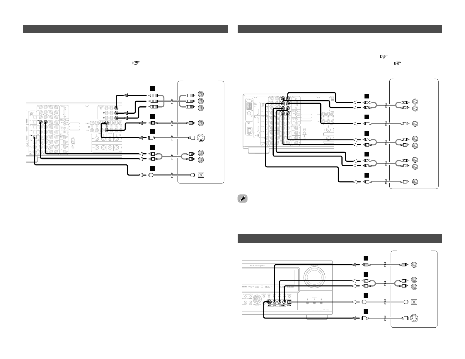
Connecting a TV tuner
G
H
A
TV
S VIDEO
OUT
R
L
AUDIO OUT
VIDEO
OUT
COMPONENT VIDEO OUT
Y
P
B
PR
R
L
R
L
I
• For best picture quality choose the component video connection to your TV. S-Video and
composite video outputs are also provided if your TV does not have component video inputs.
• To connect the digital audio output from the TV, you can choose from either the coaxial or the
optical connections. If you choose to use the coaxial or the optical connection, it needs to be
assigned. For more information about Digital Input Assignment ( page 63).
17
Connecting Other Sources Connecting Other Sources
Connecting a video camera component or video game
Video camera /
Video game
S VIDEO
OUT
R
L
AUDIO OUT
VIDEO
OUT
OPTICAL
OUT
R
L
R
L
G
H
A
D
Connecting the external inputs (EXT. IN) terminals
DVD Audio-Video /
Super Audio CD Player /
External decoder
R
SURROUND
BACK
L
R
SURROUND
L
R
FRONT
L
7.1ch AUDIO OUT
CENTER
SUB-
WOOFER
R
L
R
L
R
L
R
L
B
A
B
A
R
L
R
L
A
• These terminals are for inputting multi-channel audio signals from an outboard decoder, or a
component with a different type of multi-channel decoder, such as a DVD Audio player, or a multichannel Super Audio CD player, or other future multi-channel sound format decoder.
• The video signal connection is the same as that for a DVD player ( page 8).
• For instructions on playback using the external input (EXT. IN) terminals ( page 63).
• With discs on which special copyright protection measures have been taken, however, the digital
signals may not be output from the DVD player. In this case, connect the DVD player’s analog
multi-channel output to the AVR-3806’s EXT. IN terminals for playback. Also refer to your DVD
player’s operating instructions.
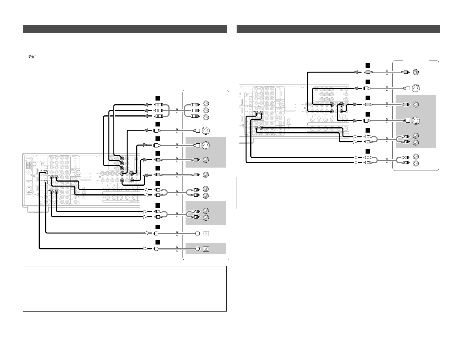
Connecting a DBS tuner
DBS / BS Tuner
S VIDEO
OUT
R
L
AUDIO OUT
VIDEO
OUT
OPTICAL
OUT
R
L
R
L
G
H
A
D
COMPONENT VIDEO OUT
Y
P
B
PR
I
• For best picture quality choose the component video connection to your DBS tuner. S-Video and
composite video outputs are also provided.
• To connect the digital audio output from the DBS tuner, you can choose from either the coaxial
or optical connections. If you choose to use the coaxial connection, it needs to be assigned. For
more information about Digital Input Assignment ( page 63).
18
Connecting Other Sources Connecting Other Sources
Connecting a DVD recorder
DVD recorder
S VIDEO
OUT
S VIDEO
IN
R
L
AUDIO IN
R
L
AUDIO OUT
VIDEO
OUT
VIDEO
IN
OPTICAL
IN
OPTICAL
OUT
R
L
R
L
G
G
H
H
A
R
L
R
L
A
D
D
COMPONENT VIDEO OUT
Y
P
B
PR
I
• For best picture quality choose the component video connection to your DVD recorder. S-Video
and composite video outputs are also provided. If you choose to use the component video
connection, it needs to be assigned. For more information about Component Input Assignment
( page 67).
• If you wish to perform analog dubbing from a digital sources, such as a DVD recorder to an analog
recorder such as a cassette deck, you will needs connect the analog inputs and outputs as shown
below, in addition to the digital audio connections.
NOTE:
• When recording to a DVD recorder, it is necessary that the type of cable used with the
playback source equipment be the same type that is connected to the AVR-3806 VCR-1 (to 2)
OUTPUT terminal.
Example: VCR-1 IN → S-Video cable : VCR-1 OUT → S-Video cable
VCR-1 IN → Video cable : VCR-1 OUT → Video cable
• Do not connect the output of the component connected to the OPTICAL 3 OUT terminal on
the AVR-3806’s rear panel to any terminal other than the OPTICAL 3 IN terminal.
Connecting a VCR
Video deck
S VIDEO
IN
R
L
AUDIO IN
R
L
AUDIO OUT
VIDEO
IN
S VIDEO
OUT
VIDEO
OUT
R
L
R
L
G
H
G
H
A
R
L
R
L
A
• There are two sets of video deck (VCR) terminals, so two video decks can be connected for
simultaneous recording or video copying.
NOTE:
• When recording to a VCR, it is necessary that the type of cable used with the playback source
equipment be the same type that is connected to the AVR-3806 VCR-1 (to 2) OUTPUT terminal.
Example: VCR-2 IN → S-Video cable : VCR-2 OUT → S-Video cable
VCR-2 IN → Video cable : VCR-2 OUT → Video cable
R
L
AUDIO OUT
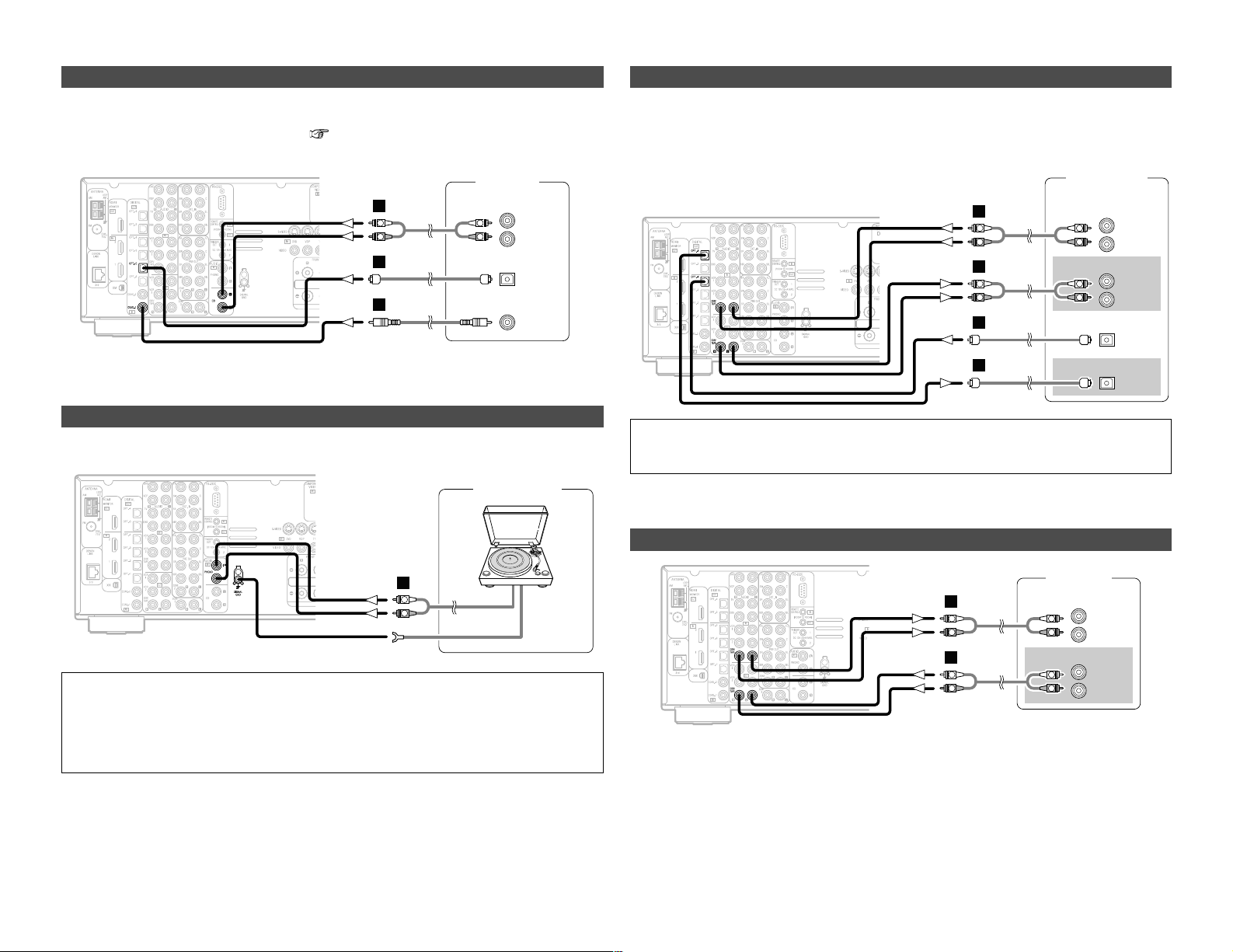
CD player
COAXIAL
OUT
OPTICAL
OUT
R
L
R
L
A
C
D
19
Connecting Other Sources Connecting Other Sources
Connecting a tape deck
Connecting a CD recorder or MD recorder
R
L
AUDIO IN
R
L
AUDIO OUT
CD recorder /
MD recorder
OPTICAL
OUT
OPTICAL
IN
R
L
R
L
A
R
L
R
L
A
D
D
If you wish to perform analog dubbing from a digital source, such as a CD or MD recorder to an
analog recorder such as a cassette deck, you will need to connect the analog inputs and outputs
as shown below, in addition to the digital audio connections.
NOTE:
• Do not connect the output of the component connected to the OPTICAL 4 OUT terminal on
the AVR-3806’s rear panel to any terminal other than the OPTICAL 4 IN terminal.
NOTE:
• The phono input can accept signals from moving magnet (MM) and high output moving coil
(MC) phono cartridges. If your turntable is equipped with a low output MC cartridge, you will
need to use a separate MC head amplifier or step-up MC transformer.
• If humming or other noise is generated when the ground wire is connected, disconnect the
ground wire.
Connecting a CD player
To connect the digital audio output from the CD player, you can choose from either the coaxial or
optical connections. If you choose to use the optical connection, it needs to be assigned. For more
information about Digital Input Assignment ( page 63).
Connecting a turntable
You can connect the turntable (MM cartridge) to the PHONO terminals.
AUDIO OUT
GND
Turntable
R
L
A
R
L
AUDIO IN
R
L
AUDIO OUT
Tape deck
R
L
R
L
A
R
L
R
L
A
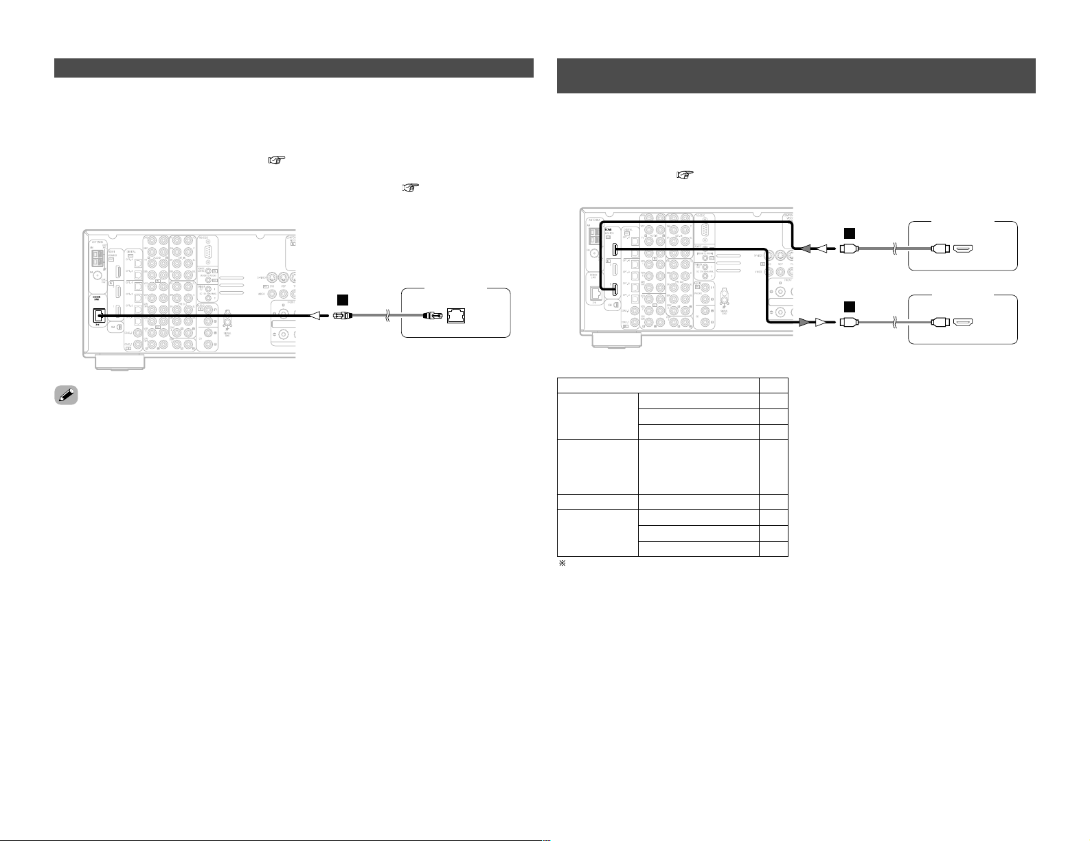
20
Connecting Other Sources Connecting Other Sources
DENON LINK connections
• High quality digital sound with reduced digital signal transfer loss can be enjoyed by connecting
a separately sold DENON LINK compatible DVD player.
• Digital transfer and multi-channel playback of DVD Audio discs, Super Audio CDs and other multichannel sources are possible by connecting the AVR-3806 to a DENON DVD player equipped with
a DENON LINK connector using the connection cable included with the DVD player. For
instructions on playing Super Audio CDs ( page 59).
• When a DENON DVD player and the DENON LINK have been connected, be sure to make a
setting to “DENON LINK” with “Setting the Digital In Assignment” ( page 63).
Connecting equipment with HDMI (High-Definition Multimedia
Interface) terminals
• A simple 1-cable connection (using a commercially available cable) with a device having an HDMI
(High-Definition Multimedia Interface) connector allows digital transfer of the digital images of
DVD video and other sources, and the multi-channel sound of DVD Audio and DVD Video.
• To provide audio output from AVR-3806’s audio output connector, select “Amp” at the System Setup.
To provide audio output from the TV, select “TV” at the System Setup. For details, see “Setting
the HDMI In Assign” ( page 66, 67).
• With discs on which special copyright protection measures have been taken, however, the digital
signals may not be output from the DVD player. In this case, connect the DVD player’s analog
multi-channel output to the AVR-3806’s EXT. IN terminals for playback.
Also refer to your DVD player’s operating instructions.
CC
DVD Video
Input signals
LINEAR PCM
DTS
Dolby Digital
DVD Audio
CC
LINEAR PCM
PACKED PCM
(with CPPM /
without CPPM)
CC
CC
CC
CD LINEAR PCM
EE
Super Audio
CD
Multi area
CD area
Stereo area
EE
CC
2 Copyright Protection System
To play back the digital video and audio of DVD
video and DVD audio through an HDMI/DVI-D
connection, both the connected player and
monitor are required to support a copyright
protection system called HDCP (Highbandwidth Digital Content Protection System).
HDCP is copy protection technology that
comprises data encryption and authentication
of the partner equipment.
The AVR-3806 supports HDCP. Please see the
user’s manual of your video display for more
information about this.
The AVR-3806 is HDMI Ver. 1.1 compatible.
J
J
DVD player
Monitor TV
HDMI
OUT
HDMI
IN

21
Connecting Other Sources Connecting Other Sources
• If your digital TV monitor or DVD player only supports DVI-D, please obtain and use an HDMI-DVI
conversion cable or adaptor, available from your dealer.
2 Connections with an HDMI/DVI-D conversion cable (adapter)
• The HDMI video stream signals (video signals) are theoretically compatible with DVI-D. When
connecting to a monitor, etc., equipped with DVI-D terminals, it is possible to connect using an
HDMI/DVI-D conversion cable, but depending on the combination of devices used the image
might not be output.
• When using an HDMI/DVI-D conversion adapter, the image may not be output properly due to
poor contact with the connected cable, etc..
NOTE:
• The audio signals on the multi/stereo area of Super Audio CDs are not output. If the Super
Audio CD is a hybrid CD, only the audio signals in the CD area are output.
• Use a compatible player to play DVD Audio discs that are copyright protected by CPPM.
• Among the devices that support HDMI, some devices can control other devices via the HDMI
connector; however, the AVR-3806 cannot be controlled by another device via the HDMI
connector.
• The audio signals from the HDMI connector (including the sampling frequency and bit length)
may be limited by the equipment that is connected.
• The video signals are not output properly if a device not compatible with HDCP is used.
• Use an HDMI monitor compatible with an HDMI input resolution of 480i or 576i.
• The video signals input from the HDMI input terminals are output to the HDMI monitor with
their original resolution, so the image will not be displayed if the resolutions of the input signal
and the monitor being used are not matched. In this case, change the setting of the resolution
on the source device (player) to one which the monitor can handle.
• For stable signal transfer, we recommend using cables that are a maximum of 5 meters in
length.

22
Connecting Other Sources Connecting Other Sources
2 AM loop antenna assembly
Connect to the AM
antenna terminals.
Remove the vinyl tie
and take out the
connection line.
Bend in the reverse
direction.
a. With the antenna
on top any stable
surface.
b. With the antenna
attached to a wall.
Mount
Installation hole Mount on wall, etc.
NOTE:
• Do not connect two FM antennas
simultaneously.
• Even if an external AM antenna is used, do
not disconnect the AM loop antenna.
• Make sure the AM loop antenna lead
terminals do not touch metal parts of the
panel.
An F-type FM antenna cable plug can be connected directly.
Connecting the antenna terminals
Note to CATV system installer:
This reminder is provided to call the CATV
system installer’s attention to Article 820-40
of the NEC which provides guidelines for
proper grounding and, in particular, specifies
that the cable ground shall be connected to
the grounding system of the building, as
close to the point of cable entry as practical.
Connection of AM antennas
1. Push the lever.
2. Insert the conductor.
3. Return the lever.
DIRECTION OF
BROADCASTING
STATION
75 Ω/ohms
COAXIAL
CABLE
FM ANTENNA
FM INDOOR
ANTENNA
(Supplied)
AM LOOP
ANTENNA
(Supplied)
AM OUTDOOR ANTENNA
GROUND
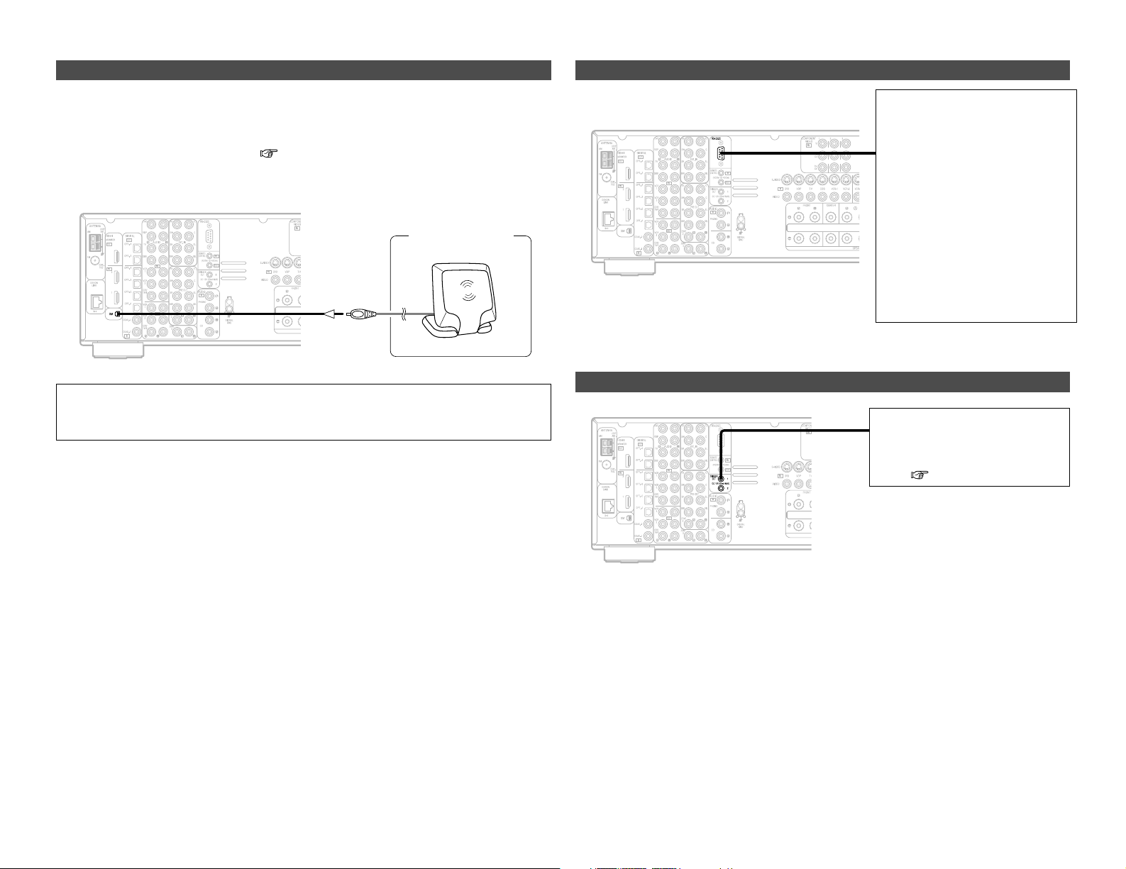
23
Connecting Other Sources Connecting Other Sources
Connecting the XM terminal
• AVR-3806 is the XM Ready® receiver. You can receive XM Satellite Radio® by connecting to the
XM Connect-and-PlayTM(sold separately) and subscribing the XM service.
• Plug the XM Connect-and-Play antenna into XM terminal on the rear panel.
• Position the XM Connect-and-Play antenna near a south-facing window to receive the best signal.
For details, see “XM Satellite Radio” ( page 45).
When making connections, also refer to the operating instructions of the XM Connect-and-Play
antenna.
NOTE:
• Keep the power supply cord unplugged until the XM Connect-and-Play antenna connection
have been completed.
Connecting the CONTROL terminal
This terminal is used for an external
controller.
Perform the following operation
before using an external controller
connected to the RS-232C terminal:
1. Press the ON/STANDBY switch
on the main unit and set the unit
to the operating mode.
2. Perform the operation to turn off
the power from the external
control.
3. Check that the product has been
set to the standby mode.
After checking the above, check the
connections of the external
controller. Operation is possible.
Connecting the TRIGGER OUT terminals
Turn the DC 12V voltage on and off
for the individual functions and
surround modes.
For details, see “Setting the Trigger
Out” ( page 73).
XM Connect-and
-Play Antenna
XM
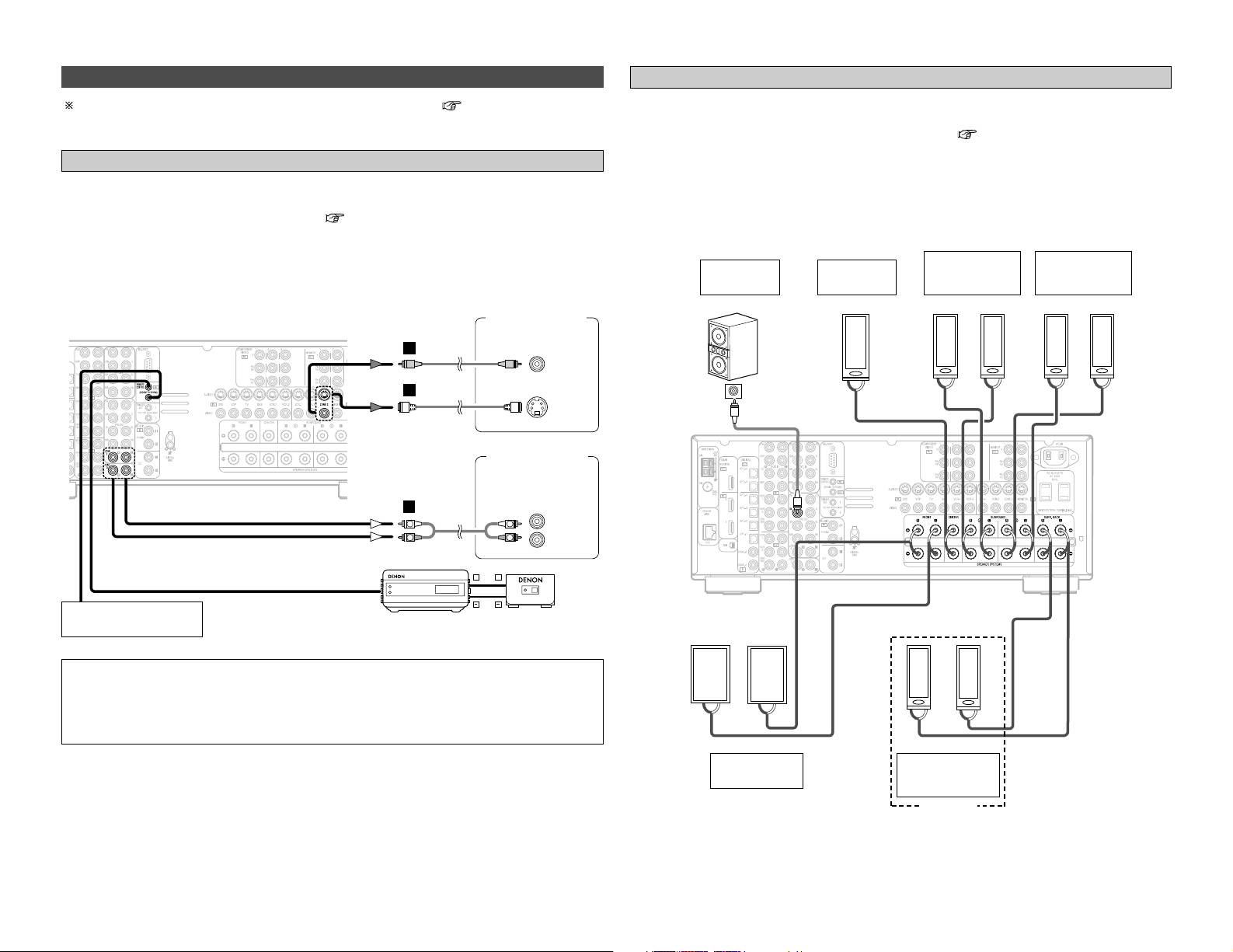
24
Connecting Other Sources Connecting Other Sources
For instructions on operations using the MULTI ZONE functions ( page 56~58).
Connecting the MULTI ZONE terminals
• If another power amplifier or pre-main (integrated) amplifier is connected, the ZONE2 pre-out
(variable) and ZONE3 pre-out (fixed level) terminals can be used to play a different program
source in ZONE2 (or ZONE3) the same time ( page 56).
• The ZONE2 video out is only for the ZONE2.
• When a sold separately room-to-room remote control unit (DENON RC-616, 617 or 618) is wired
and connected between the MAIN ZONE and ZONE2 (ZONE3), the remote-controllable devices
in the MAIN ZONE can be controlled from ZONE2 (ZONE3) using the remote control unit.
ZONE2 (or ZONE3) pre-out connections
NOTE:
• For the AUDIO output, use high quality pin-plug cables and wire in such a way that there is no
humming or noise.
• For instructions on installation and operation of separately sold devices, refer to the devices’
operating instructions.
• When the surround back’s power amplifier is assigned to the ZONE2 or ZONE3 output channel
at “Power Amp Assign” in the “System Setup Menu”, the surround back speaker terminals can
be used as the ZONE2 or ZONE3 speaker out terminals ( page 57).
• The connections diagram below is an example for when the surround back speaker is assigned
to the ZONE2 stereo 2 channel.
In this case, surround back speaker out can not be used for MAIN ZONE.
ZONE2 / ZONE3 speaker out connections
Extension terminal
for future use.
Monitor TV
(ZONE 2)
Power amplifier
(ZONE 2)
Premain amplifier
(ZONE 3)
><
><
><
><><><><
><
><
IN
(R) (L) (L) (R)
(L)
(R)
(L)
(R)
Connection
terminal for
subwoofer
with built-in
amplifier
(subwoofer),
etc.
Surround
speaker
systems (A)
Subwoofer
Surround
speaker
systems (B)
ZONE2
Front speaker
systems
Front speaker
systems
Center
speaker
ZONE2
Monitor TV
(ZONE2)
AUX OUT
G
H
A
L
R
RC-616
INFRARED
RETRANSMITTER
Power amplifier
Premain amplifier
INPUT OUTPUT
+
+
L
R
INFRARED
(ZONE2)
(ZONE3)
L
R
RC-617
SENSOR
VIDEO
IN
S VIDEO
IN
IN

25
Connecting Other Sources Connecting Other Sources
• Use these terminals if you wish to connect external power amplifier(s) to increase the power of
the front, center, surround and surround back sound channels, or for connection to powered
loudspeakers.
• When using only one surround back speaker, connect it to the left channel.
Connecting the pre-out terminals
Power amplifier
R
SURROUND
BACK
L
R
SURROUND
L
R
FRONT
L
CENTER
SUB-
WOOFER
R
L
R
L
B
A
B
A
R
L
R
L
R
L
R
L
A
Connecting the power supply cord
AC 120 V, 60 Hz
AC outlets
(wall)
Power supply cord
(Supplied)
NOTE:
• Only use the AC OUTLETS for audio equipment. Never use it for hair driers, TVs or other
electrical appliances.
• Insert the plugs securely. Incomplete connections will result in the generation of noise.
AC OUTLETS
• SWITCHED (total capacity – 120 W (1 A.))
The power to the outlet is turned on and off in
conjunction with the POWER switch on the
main unit, and when the power is switched
between on and standby from the remote
control unit.
No power is supplied from this outlet when
this unit’s power is at standby. Never connect
equipment whose total power consumption
exceeds 120 W (1 A.).
Loading…
Denon AVR-3806
AV SURROUND RECEIVER
OPERATING INSTRUCTIONS
BEDIENUNGSANLEITUNG
MODE D’EMPLOI
ISTRUZIONI PER L’USO
INSTRUCCIONES DE FUNCIONAMIENTO
GEBRUIKSAANWIJZING
BRUKSANVISNING
Manual
View the manual for the Denon AVR-3806 here, for free. This user manual comes under the category receivers and has been rated by 13 people with an average of a 8. This manual is available in the following languages: English. Do you have a question about the Denon AVR-3806?
Ask your question here
Product Images (2)

Denon AVR-3806 specifications
Below you will find the product specifications and the manual specifications of the Denon AVR-3806.
The Denon AVR-3806 is a home theater receiver designed to provide immersive audio experiences. It supports a wide range of audio formats, including Dolby Digital, DTS, and Dolby Pro Logic IIx. With a power output of 120 watts per channel, it delivers clear and powerful sound that fills the room. The receiver features the Audyssey MultEQ XT room correction system, which helps optimize the sound quality based on the room’s acoustics. It also has a built-in AM/FM tuner and supports digital radio stations, including HD Radio and XM Satellite Radio. The AVR-3806 has multiple inputs and outputs, including HDMI, component video, S-video, and composite video. It also supports digital audio inputs, including optical and coaxial. With the HDMI interface, it provides high-quality video and audio signals, making it an ideal addition to any home theater system. The receiver can be controlled through a variety of methods, including a remote control, a web browser, and RS-232C, making it easy to operate no matter how complex your home theater setup may be.
General
| Brand | Denon |
| Model | AVR-3806 | AVR-3806 |
| Product | receiver |
| Language | English |
| Filetype | Manual (PDF) |
Frequently asked questions
Can’t find the answer to your question in the manual? You may find the answer to your question in the FAQs about the Denon AVR-3806 below.
Can bluetooth devices of different brands be connected to each other?
Yes, bluetooth is a universal method that allows different devices equipped with bluetooth to connect to each other.
What is bluetooth?
Bluetooth is a way of exchanging data wirelessly between electronic devices via radio waves. The distance between the two devices that exchange data can in most cases be no more than ten metres.
What is HDMI?
HDMI stands for High-Definition Multimedia Interface. An HDMI cable is used to transport audio and video signals between devices.
When is my volume too loud?
A volume above 80 decibels can be harmful to hearing. When the volume exceeds 120 decibels, direct damage can even occur. The chance of hearing damage depends on the listening frequency and duration.
How can I best clean my receiver?
A slightly damp cleaning cloth or soft, dust-free cloth works best to remove fingerprints. Dust in hard-to-reach places is best removed with compressed air.
Wat is Dolby Atmos?
Dolby Atmos is a technology that ensures that the sound is reflected from the ceiling to where you are listening. This makes it possible to create a 5.1 effect with only 1 speaker.
Is the manual of the Denon AVR-3806 available in English?
Yes, the manual of the Denon AVR-3806 is available in English .
Is your question not listed? Ask your question here
- Addeddate
- 2022-01-15 04:32:08
- Identifier
- manuallib-id-2498169
- Identifier-ark
- ark:/13960/s2r4g5d9stj
- Ocr
- tesseract 5.0.0-1-g862e
- Ocr_autonomous
- true
- Ocr_detected_lang
- zh
- Ocr_detected_lang_conf
- 1.0000
- Ocr_detected_script
-
HanS
HanT
Latin
Japanese
Cyrillic
- Ocr_detected_script_conf
-
0.1545
0.1545
0.5818
0.0580
0.0512
- Ocr_module_version
- 0.0.14
- Ocr_parameters
- -l lat+chi_sim+ltz+que+swa+Latin+HanS
- Page_number_confidence
- 90.98
comment
Reviews
There are no reviews yet. Be the first one to
write a review.
55
Views
DOWNLOAD OPTIONS
Temporarily Unavailable
DAISY
For users with print-disabilities
Temporarily Unavailable
EPUB
Uploaded by
chris85
on
Denon AVR-3806 IR Codes
IR Codes
6 pages
en
Control Protocol
18 pages
en
Operating Instructions
142 pages
en
Denon AVR-3806 Specification
The Denon AVR-3806 is a high-performance AV receiver designed to cater to home theater enthusiasts seeking both versatility and superior sound quality. It features a 7.1-channel configuration, delivering robust audio experiences through its advanced processing capabilities. With a power output of 120 watts per channel, the AVR-3806 ensures dynamic and immersive sound reproduction across all connected speakers. The receiver supports Dolby Digital EX, DTS-ES, and Dolby Pro Logic IIx, providing rich surround sound options that enhance cinematic audio experiences.
Connectivity is a highlight, with a wide array of inputs and outputs including HDMI, component, S-Video, and composite video connections, making it compatible with various audio and video sources. It includes three HDMI inputs and one output, facilitating seamless integration with modern high-definition devices. The AVR-3806 also offers multi-zone functionality, allowing users to enjoy different audio sources in separate rooms.
Equipped with Audyssey MultEQ XT technology, the receiver automatically calibrates sound settings to optimize audio performance based on the room’s acoustics. Its intuitive on-screen display and user-friendly interface simplify setup and operation, ensuring ease of use even for those new to AV systems. The AVR-3806 supports AM/FM radio with RDS, providing additional entertainment options.
Denon’s attention to detail is evident in the receiver’s build quality, featuring a sleek design that complements modern home entertainment setups. With its comprehensive feature set, the Denon AVR-3806 stands out as a versatile and powerful receiver, catering to both audiophiles and casual users looking for a reliable centerpiece for their home theater systems.
Denon AVR-3806 F.A.Q.
To reset the Denon AVR-3806 to factory settings, turn off the unit. Then, while holding down the ‘Power’ button and ‘Speaker A’ button, press and hold the ‘Power ON/STANDBY’ button. Release the buttons when the display starts flashing.
First, check all speaker connections and ensure they are properly connected. Verify that the mute function is not activated and the correct input source is selected. If the problem persists, try resetting the microprocessor by following the factory reset instructions.
Connect the front, center, surround, and subwoofer speakers to the corresponding speaker terminals on the AVR-3806. Then, configure the speaker setup in the system setup menu to 5.1 mode, specifying the size and distance of each speaker.
Unfortunately, the Denon AVR-3806 does not support firmware updates via USB or network connections. Check Denon’s official website or contact support for any available updates or instructions.
Ensure that the HDMI cable is securely connected to both the AVR-3806 and the TV. Check that the correct HDMI input is selected on the TV. If the issue continues, test with a different HDMI cable or input to rule out cable or port issues.
Turn off and unplug the AVR-3806. Use a soft, dry cloth to gently wipe the exterior. Avoid using any liquid cleaners or spraying directly on the unit to prevent damage.
Use an audio cable with a 3.5mm jack on one end and RCA connectors on the other. Connect the 3.5mm end to your smartphone’s headphone jack and the RCA ends to an available input on the AVR-3806. Select the respective input source on the receiver.
The Denon AVR-3806 does not have built-in wireless speaker support. However, you can use a wireless speaker kit to connect the AVR-3806 to wireless speakers by connecting the kit’s transmitter to the receiver’s speaker outputs.
Use the built-in Auto Setup function with the included calibration microphone. Connect the microphone to the setup mic jack, place it at the listening position, and follow the on-screen instructions to calibrate the speakers.
Ensure that the unit is placed in a well-ventilated area and not enclosed in a cabinet. Check that the ventilation slots are not obstructed. If overheating persists, consider using an external cooling fan.
Denon AVR3806 Receiver PDF User Guides and Manuals for Free Download: Found (9) Manuals for Denon AVR3806 Device Model (Code List, Specifications, Guía Del Usuario)
The Denon AVR3806 is a standout model in the world of audio-video receivers, combining advanced technology with remarkable sound quality. This device caters to both home theater enthusiasts and casual audio lovers alike. With its robust feature set and superior build, it promises to elevate your audio-visual experience, making it a solid investment for anyone interested in immersive entertainment.
One of the most striking features of the Denon AVR3806 is its power. It offers 8 channels with a total output of 120 watts per channel, which allows it to drive various speaker setups without breaking a sweat. This level of power is not just about volume; it translates to clearer dialogue and more impactful sound effects in movies, enhancing the overall viewing experience. Whether you’re watching a slow-paced drama or an action-packed thriller, the AVR3806 handles it all with finesse.
In terms of connectivity, the Denon AVR3806 is exceptionally well-equipped. It includes multiple HDMI inputs, making it easy to connect various devices such as Blu-ray players, gaming consoles, and streaming devices. This versatility means you won’t have to constantly swap cables, resulting in a more streamlined setup. Moreover, the AVR3806 supports various audio formats, including Dolby TrueHD and DTS-HD Master Audio, ensuring that you enjoy high-fidelity sound from every source.
Another standout feature is the Audyssey MultEQ room acoustic correction technology. This innovative feature analyzes the acoustic characteristics of your room and automatically adjusts the receiver’s sound profile to ensure optimal audio performance. This means that regardless of the layout of your living space, the AVR3806 fine-tunes itself to deliver the richest sound possible. It’s one of those features that you might not think about, but once you’ve experienced it, it’s hard to go back.
Beyond its sound and connectivity features, the user interface of the Denon AVR3806 is intuitive and user-friendly. The on-screen setup guide simplifies the installation process, making it accessible even for those who may not be tech-savvy. The remote control is also well-designed, allowing for easy navigation through the various settings and functions. This attention to user experience truly sets the AVR3806 apart from its competitors.
Here’s a quick summary of the key features of the Denon AVR3806:
- 8 Channels: 120 Watts per channel for powerful audio output.
- Multiple HDMI Inputs: Connects easily to various audio and video devices.
- Supports High-Fidelity Formats: Compatible with Dolby TrueHD and DTS-HD Master Audio.
- Audyssey MultEQ: Automatic room acoustic correction for better sound quality.
- User-Friendly Interface: Simplified on-screen setup guide and intuitive remote control.
In conclusion, the Denon AVR3806 is a formidable receiver that excels in delivering top-notch audio quality, user-friendly features, and flexible connectivity options. Whether you’re a dedicated audiophile or just someone looking to enhance your home theater setup, investing in the AVR3806 is a decision you won’t regret. Its exceptional performance can transform your movie nights and music listening into memorable experiences.