

1
Contents
Contents
2
3
6
LAN Port LED Status Table …………………………………………………………………………….6
7
CPU Socket …………………………………………………………………………………………………..8
DIMM Slots……………………………………………………………………………………………………9
PCI_E1~2: PCIe Expansion Slots ……………………………………………………………………..9
M2_1: M.2 Slot …………………………………………………………………………………………….10
SATA1~4: SATA 6Gb/s Connectors …………………………………………………………………10
JFP1, JFP2: Front Panel Connectors ……………………………………………………………..11
JAUD1: Front Audio Connector ……………………………………………………………………..11
ATX_PWR1, CPU_PWR1: Power Connectors …………………………………………………..12
JUSB1, JUSB2: USB 2.0 Connectors ………………………………………………………………13
JUSB3: USB 3.2 Gen1 Connector …………………………………………………………………..13
CPU_FAN1, SYS_FAN1: Fan Connectors ………………………………………………………..14
JTPM1: TPM Module Connector …………………………………………………………………….14
JCI1: Chassis Intrusion Connector …………………………………………………………………15
JCOM1: Serial Port Connector ………………………………………………………………………15
JBAT1: Clear CMOS (Reset BIOS) Jumper ………………………………………………………16
EZ Debug LED ……………………………………………………………………………………………..16
17
BIOS Setup ………………………………………………………………………………………………….18
Entering BIOS Setup …………………………………………………………………………………….18
Resetting BIOS …………………………………………………………………………………………….18
Updating BIOS……………………………………………………………………………………………..19
20
Installing Windows® 10 …………………………………………………………………………………20
Installing Drivers …………………………………………………………………………………………20
Installing Utilities ………………………………………………………………………………………..20
Thank you for purchasing the MSI®
motherboard. This User Guide gives information about
board layout, component overview, BIOS setup and software
installation.

2
The components included in this package are prone to damage from electrostatic
discharge (ESD). Please adhere to the following instructions to ensure successful
computer assembly.
Ensure that all components are securely connected. Loose connections may cause
the computer to not recognize a component or fail to start.
Hold the motherboard by the edges to avoid touching sensitive components.
It is recommended to wear an electrostatic discharge (ESD) wrist strap when
handling the motherboard to prevent electrostatic damage. If an ESD wrist strap is
not available, discharge yourself of static electricity by touching another metal object
before handling the motherboard.
Store the motherboard in an electrostatic shielding container or on an anti-static
pad whenever the motherboard is not installed.
Before turning on the computer, ensure that there are no loose screws or metal
components on the motherboard or anywhere within the computer case.
Do not boot the computer before installation is completed. This could cause
permanent damage to the components as well as injury to the user.
If you need help during any installation step, please consult a certified computer
technician.
Always turn off the power supply and unplug the power cord from the power outlet
before installing or removing any computer component.
Keep this user guide for future reference.
Keep this motherboard away from humidity.
Make sure that your electrical outlet provides the same voltage as is indicated on
the PSU, before connecting the PSU to the electrical outlet.
Place the power cord such a way that people can not step on it. Do not place
anything over the power cord.
All cautions and warnings on the motherboard should be noted.
If any of the following situations arises, get the motherboard checked by service
personnel:
Liquid has penetrated into the computer.
The motherboard has been exposed to moisture.
The motherboard does not work well or you can not get it work according to
user guide.
The motherboard has been dropped and damaged.
The motherboard has obvious sign of breakage.
Do not leave this motherboard in an environment above 60°C (140°F), it may
damage the motherboard.

3
Support 3rd Gen AMD Ryzen™ Desktop Processors and AMD
Ryzen™4000 G-Series Desktop Processors
AMD B550 Chipset (B550M-A PRO)
AMD A520 Chipset (A520M-A PRO)
2x DDR4 memory slots, support up to 64GB*
Supports DDR4 1866/ 2133/ 2400/ 2667/ 2800/ 2933/
3000/ 3066/ 3200 MHz by JEDEC
Supports DDR4 2667/ 2800 /2933 /3000 /3066 /3200
/3466 /3600/ 3733 /3866 /4000 /4133 /4266 /4400/ 4600+
MHz by A-XMP OC MODE
1DPC 1R max speed 4600 MHz
1DPC 2R max speed 3866 MHz
Dual channel memory architecture
Supports non-ECC UDIMM memory
Supports ECC UDIMM memory (non-ECC mode)
Supports un-buffered memory
* Please refer www.msi.com for more information on
compatible memory.
1x PCIe 3.0 x1 slot
1x PCIe x16 slot
B550M-A PRO supports PCIe 4.0/3.0*
A520M-A PRO supports PCIe 3.0
* PCIe specifications may vary depending on the CPU
installed.
1x HDMI 2.1 port, supporting a maximum resolution of
4096×2160 @60Hz*/**
1x DVI-D port, supporting a maximum resolution of
1920×1200 @60Hz*
Maximum shared memory of 16GB
* Available for the processor with integrated graphics.
** Graphics specifications may vary depending on the CPU
installed.
Realtek® ALC892 Codec
7.1-Channel High Definition Audio
Continued on next page

4
Continued from previous page
1x Realtek® RTL8111H 1Gbps LAN controller
AMD B550/A520 Chipset
4x SATA 6Gb/s ports
1x M.2 slot (Key M) (from AMD Processor)
B550M-A PRO supports PCIe 4.0/3.0*
A520M-A PRO supports PCIe 3.0
Supports SATA 6Gb/s
Supports 2242/ 2260/ 2280 storage devices
* PCIe specifications may vary depending on the CPU
installed.
AMD B550/A520 Chipset
2x USB 3.2 Gen 1 5Gbps ports are available through the
internal USB 3.2 Gen 1 5Gbps connector
6x USB 2.0 ports (2 Type-A ports on the back panel, 4
ports through the internal USB 2.0 connectors)
AMD Processor
4x USB 3.2 Gen 1 5Gbps Type-A ports on the back panel
1x 24-pin ATX main power connector
1x 4-pin ATX 12V power connector
4x SATA 6Gb/s connectors
1x M.2 slots (M-Key)
1x USB 3.2 Gen 1 5Gbps connector (supports additional 2
USB 3.2 Gen 1 5Gbps ports)
2x USB 2.0 connectors (supports additional 4 USB 2.0 ports)
1x 4-pin CPU fan connector
1x 4-pin system fan connector
1x Front panel audio connector
2x System panel connectors
1x Chassis Intrusion connector
1x TPM module connector
1x Clear CMOS jumper
Continued on next page

Continued from previous page
1x HDMI port
1x DVI-D port
1x PS/2 mouse port
1x PS/2 keyboard port
4x USB 3.2 Gen 1 5Gbps Type-A ports
2x USB 2.0 Type-A ports
1x LAN (RJ45) port
3x audio jacks
NUVOTON NCT6687-R Controller Chip
CPU/ System/ Chipset temperature detection
CPU/ System fan speed detection
CPU/ System fan speed control
mATX Form Factor
9.3 in. x 7.9 in. (23.6 cm x 20 cm)
1x 256 Mb flash
UEFI AMI BIOS
ACPI 6.0, SMBIOS 2.8
Multi-language
Drivers
DRAGON CENTER
CPU-Z MSI GAMING
Google Chrome™, Google Toolbar, Google Drive
Norton™ Internet Security Solution
User Scenario
Hardware Monitor
True Color
Live Update
Speed Up
Smart Tool
Super Charger
Please refer to http://
download.msi.com/manual/
mb/DRAGONCENTER2.pdf for
more details.

6
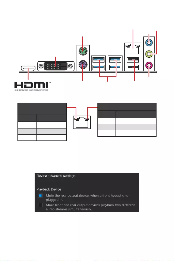
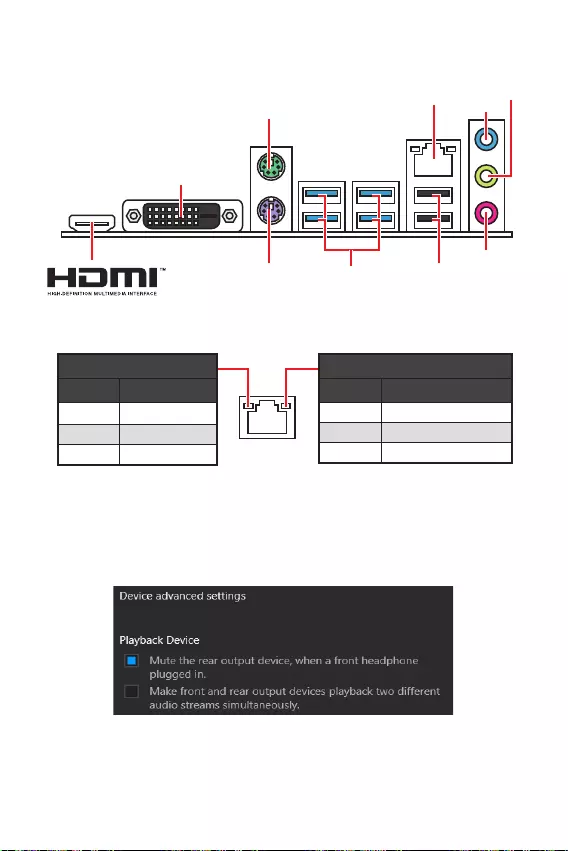
Off No link
Yellow Linked
Blinking Data activity
Off 10 Mbps connection
Green 100 Mbps connection
Orange 1 Gbps connection
To configure 7.1-channel audio, you have to connect front audio I/O module to JAUD1
connector and follow the below steps.
Click on the to open the dialog
below.
Select .
Plug your speakers to audio jacks on rear and front I/O panel. When you plug into
a device at an audio jack, a dialogue window will pop up asking you which device
is current connected.
USB 3.2 Gen 1
(5Gbps) Type-A
PS/2 Keyboard
PS/2 Mouse
LAN Line-in
Mic in
Line-out
DVI-D
USB 2.0 Type-A

7
* Distance from the center of the CPU to the nearest DIMM slot.
M2_1
JTPM1
JUSB2
JUSB1
CPU_FAN1
SYS_FAN1
PCI_E1
PCI_E2
Processor Socket
CPU_PWR1
JCI1
JCOM1
JAUD1 JFP1
JFP2
ATX_PWR1
SATA4
SATA3
SATA2
SATA1
JUSB3
JBAT1
DIMMB1
DIMMA1
50.89mm*

8
Please install the CPU into the CPU socket as shown below.
1
3
4
6
7
8
2
Always unplug the power cord from the power outlet before installing or removing
the CPU.
Please retain the CPU protective cap after installing the processor. MSI will deal
with Return Merchandise Authorization (RMA) requests if only the motherboard
comes with the protective cap on the CPU socket.
When installing a CPU, always remember to install a CPU heatsink. A CPU heatsink
is necessary to prevent overheating and maintain system stability.
your system.
Overheating can seriously damage the CPU and motherboard. Always make sure
the cooling fans work properly to protect the CPU from overheating. Be sure to apply
an even layer of thermal paste (or thermal tape) between the CPU and the heatsink to
enhance heat dissipation.
If you purchased a separate CPU and heatsink/ cooler, Please refer to the docu-
mentation in the heatsink/ cooler package for more details about installation.

9
Please install the memory module into the DIMM slot as shown below.
1
1
2
3
3
2
Due to chipset resource usage, the available capacity of memory will be a little less
than the amount of installed.
Please note that the maximum capacity of addressable memory is 4GB or less
for 32-bit Windows OS due to the memory address limitation. Therefore, we recom—
mended that you to install 64-bit Windows OS if you want to install more than 4GB
memory on the motherboard.
If you install a large and heavy graphics card, you need to use a tool such as
to support its weight to prevent deformation
of the slot.
unplug the power supply power cable from the power outlet. Read the expansion
card’s documentation to check for any necessary additional hardware or software
changes.
PCIe 4.0/ 3.0 x16 (CPU)
PCIe 3.0 x1 (PCH)

10
These connectors are SATA 6Gb/s interface ports. Each connector can connect to one
SATA device.
SATA3
SATA4
SATA1
SATA2
Please do not fold the SATA cable at a 90-degree angle. Data loss may result
during transmission otherwise.
SATA cables have identical plugs on either sides of the cable. However, it is
saving purposes.
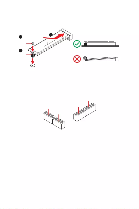
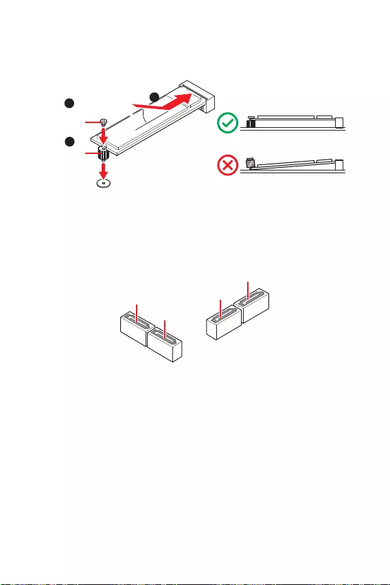
Please install the M.2 device into the M.2 slot as shown below.
1
3
Standoff
Supplied
M.2 screw 30º30º
2

11
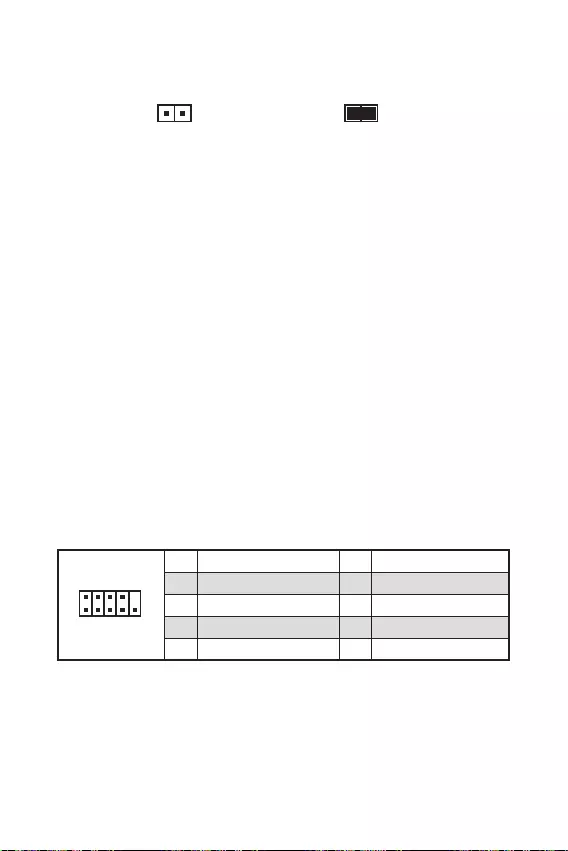
These connectors connect to the switches and LEDs on the front panel.
1
2 10
9
+
+
+— ——
—
+
Power LED
HDD LED Reset Switch
Reserved
Power Switch 1 HDD LED + 2 Power LED +
3 HDD LED — 4 Power LED —
5 Reset Switch 6 Power Switch
7 Reset Switch 8 Power Switch
9 Reserved 10 No Pin
JFP2 1
+
+—
—
Speaker
Buzzer 1 Speaker — 2 Buzzer +
3 Buzzer — 4 Speaker +
HDD LED
RESET SW
HDD LED HDD LED —
HDD LED +
POWER LED —
POWER LED +
POWER LED
JFP1
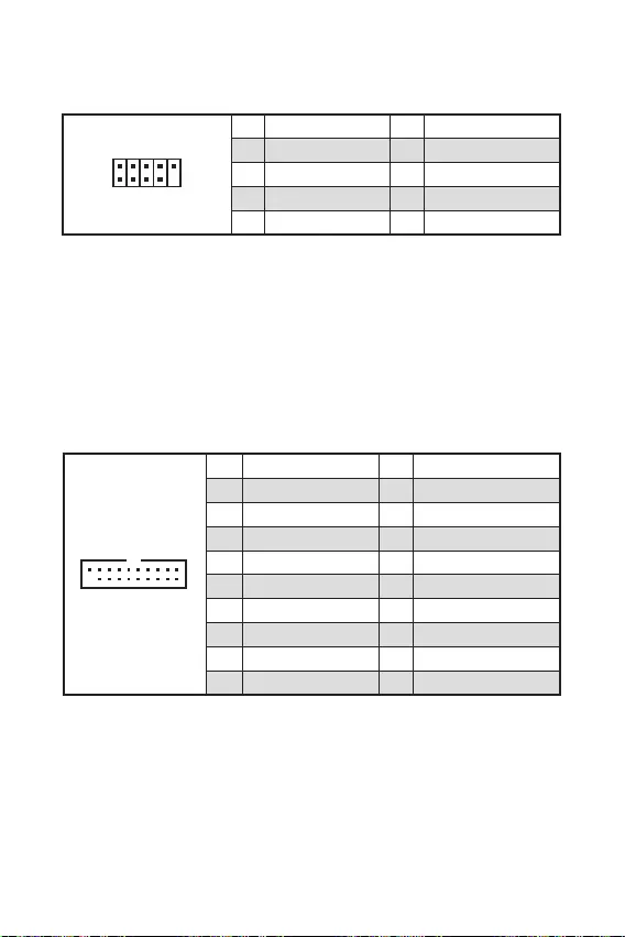
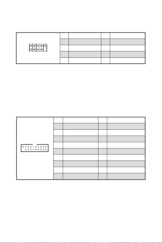
This connector allow you to connect audio jacks on the front panel.
1
2 10
9
1 MIC L 2 Ground
3 MIC R 4 NC
5 Head Phone R 6 MIC Detection
7 SENSE_SEND 8 No Pin
9 Head Phone L 10 Head Phone Detection

12
These connectors allow you to connect an ATX power supply.
Make sure that all the power cables are securely connected to a proper ATX power
supply to ensure stable operation of the motherboard.
24
131
12
ATX_PWR1
1 +3.3V 13 +3.3V
2 +3.3V 14 -12V
3 Ground 15 Ground
4 +5V 16 PS-ON#
5 Ground 17 Ground
6 +5V 18 Ground
7 Ground 19 Ground
8 PWR OK 20 Res
9 5VSB 21 +5V
10 +12V 22 +5V
11 +12V 23 +5V
12 +3.3V 24 Ground
3
2 1
4CPU_PWR1
1 Ground 3 +12V
2 Ground 4 +12V

13
These connectors allow you to connect USB 3.2 Gen1 ports on the front panel.
110
11
20
1 Power 11 USB2.0+
2 USB3_RX_DN 12 USB2.0-
3 USB3_RX_DP 13 Ground
4 Ground 14 USB3_TX_C_DP
5 USB3_TX_C_DN 15 USB3_TX_C_DN
6 USB3_TX_C_DP 16 Ground
7 Ground 17 USB3_RX_DP
8 USB2.0- 18 USB3_RX_DN
9 USB2.0+ 19 Power
10 NC 20 No Pin
Note that the Power and Ground pins must be connected correctly to avoid possible
damage.
These connectors allow you to connect USB 2.0 ports on the front panel.
1
2 10
9
1 VCC 2 VCC
3 USB0- 4 USB1-
5 USB0+ 6 USB1+
7 Ground 8 Ground
9 No Pin 10 NC
Note that the VCC and Ground pins must be connected correctly to avoid possible
damage.
In order to recharge your iPad,iPhone and iPod through USB ports, please install
MSI® SUPER CHARGER software.
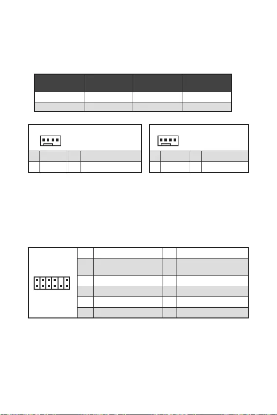
14
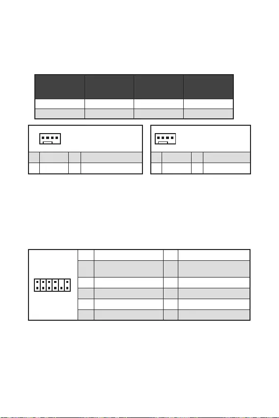
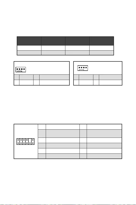
You can adjust fan speed in
PWM Mode fan connectors provide constant 12V output and adjust fan speed with
speed control signal. When you plug a 3-pin (Non-PWM) fan to a fan connector in
PWM mode, the fan speed will always maintain at 100%, which might create a lot of
noise.
1
1 Ground 2 +12V
3 Sense 4 Speed Control Signal
CPU_FAN1 PWM mode 1A 12W
SYS_FAN1 PWM mode 1A 12W
1
1 Ground 2 Voltage Control
3 Sense 4 NC
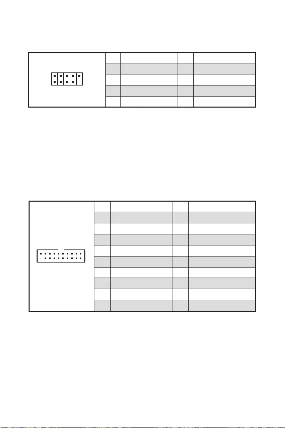
1
212
11
1 SPI Power 2 SPI Chip Select
3
Master In Slave Out (SPI
Data)
4
Master In Slave In (SPI
Data)
5 Reserved 6 SPI Clock
7 Ground 8 SPI Reset
9 Reserved 10 No Pin
11 Reserved 12 Interrupt Request
This connector is for TPM (Trusted Platform Module). Please refer to the TPM
security platform manual for more details and usages.

This connector allows you to connect the chassis intrusion switch cable.
Normal
(default) Trigger the chassis
intrusion event
Connect the connector to the chassis intrusion switch/ sensor on the
chassis.
Close the chassis cover.
Go to .
Set to .
Press F10 to save and exit and then press the key to select .
Once the chassis cover is opened again, a warning message will be displayed on
screen when the computer is turned on.
Go to .
Set to Reset.
Press to save and exit and then press the key to select .
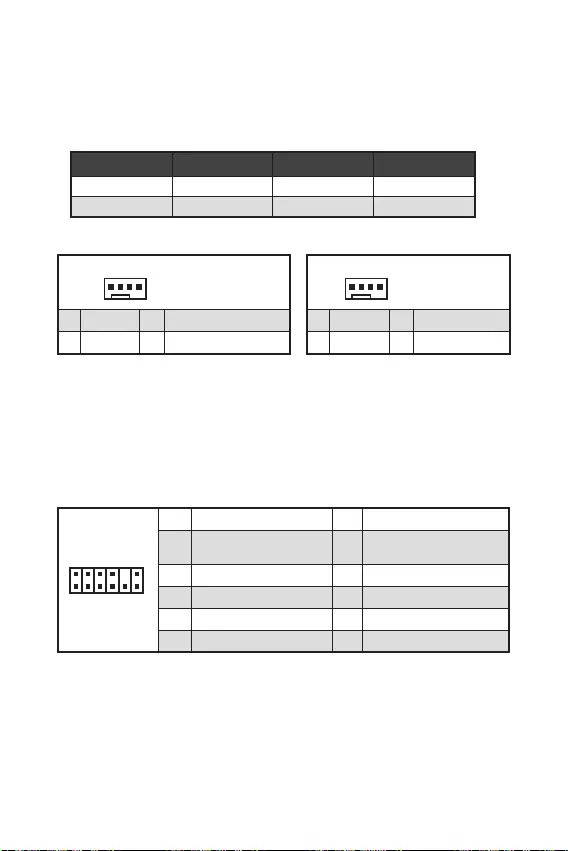
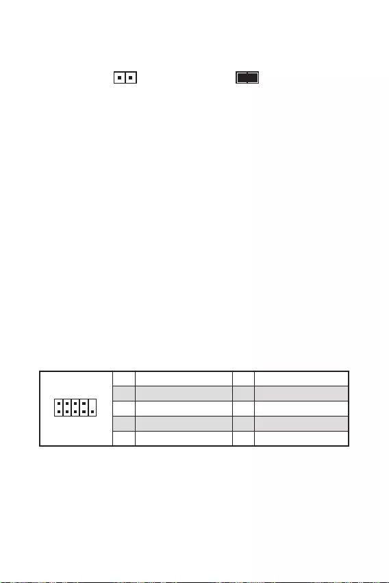
This connector allows you to connect the optional serial port with bracket.
1
2 10
9
1 DCD 2 SIN
3 SOUT 4 DTR
5 Ground 6 DSR
7 RTS 8 CTS
9 RI 10 No Pin

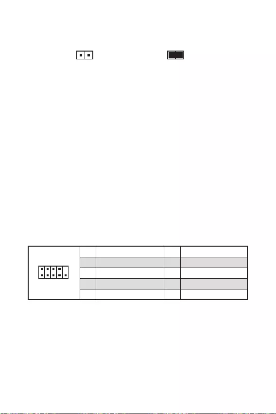
16
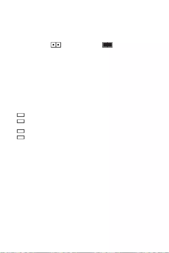
There is CMOS memory onboard that is external powered from a battery located on
the motherboard to save system configuration data. If you want to clear the system
configuration, set the jumpers to clear the CMOS memory.
Keep Data
(default) Clear CMOS/ Reset
BIOS
Power off the computer and unplug the power cord.
Use a jumper cap to short JBAT1 for about 5-10 seconds.
Remove the jumper cap from JBAT1.
Plug the power cord and power on the computer.
These LEDs indicate the status of the motherboard.
— indicates CPU is not detected or fail.
— indicates DRAM is not detected or fail.
— indicates GPU is not detected or fail.
— indicates booting device is not detected or fail.

17
MSI UEFI BIOS is compatible with UEFI (Unified Extensible Firmware Interface)
architecture. UEFI has many new functions and advantages that traditional BIOS
cannot achieve, and it will completely replace BIOS in the future. The MSI UEFI
BIOS uses UEFI as the default boot mode to take full advantage of the new chipset’s
capabilities. However, it still has a CSM (Compatibility Support Module) mode to be
compatible with older devices. That allows you to replace legacy devices with UEFI
compatible devices during the transition.
The term BIOS in this user guide refers to UEFI BIOS unless otherwise noted.
Fast booting — UEFI can directly boot the operating system and save the BIOS self-
test process. And also eliminates the time to switch to CSM mode during POST.
Supports for hard drive partitions larger than 2 TB.
Supports more than 4 primary partitions with a GUID Partition Table (GPT).
Supports unlimited number of partitions.
Supports full capabilities of new devices — new devices may not provide backward
compatibility.
Supports secure startup — UEFI can check the validity of the operating system to
ensure that no malware tampers with the startup process.
— this motherboard supports only 64-bit
Windows 10 operating system.
— the system will detect your graphics card. When display a
warning message
We recommend that you to use a GOP/ UEFI compatible graphics card.
After entering the BIOS, find the BIOS Mode at the top of the screen.

18
The default settings offer the optimal performance for system stability in normal
conditions. You should to avoid possible system
damage or failure booting unless you are familiar with BIOS.
BIOS items are continuous update for better system performance. Therefore, the
reference only. You could also refer to the information panel for BIOS item
description.
The BIOS items will vary with the processor.
Press key, when the
message appears on the screen during the boot process.
F1: General Help
F2: Add/ Remove a favorite item
F3: Enter Favorites menu
F4: Enter CPU Specifications menu
: Enter Memory-Z menu
F6: Load optimized defaults
F7: Switch between Advanced mode and EZ mode
F8: Load Overclocking Profile
F9: Save Overclocking Profile
F10: Save Change and Reset*
F12: Take a screenshot and save it to USB flash drive (FAT/ FAT32 format only).
: Enter Search page
* When you press F10, a confirmation window appears and it provides the
modification information. Select between Yes or No to confirm your choice.
You might need to restore the default BIOS setting to solve certain problems. There
are several ways to reset BIOS:
Go to BIOS and press F6 to load optimized defaults.
Short the jumper on the motherboard.
Please refer to the jumper section for resetting BIOS.

19
Before updating:
Please download the latest BIOS file that matches your motherboard model from MSI
website. And then save the BIOS file into the USB flash drive.
Updating BIOS:
Insert the USB flash drive that contains the update file into the USB port.
Please refer the following methods to enter flash mode.
Reboot and press key during POST and click on to reboot the
system.
Reboot and press key during POST to enter BIOS. Click the
button and click on to reboot the system.
Select a BIOS file to perform the BIOS update process.
When prompted click on to start recovering BIOS.
After the flashing process is 100% completed, the system will reboot
automatically.
Before updating:
Make sure the LAN driver is already installed and the internet connection is set
properly.
Updating BIOS:
Install and launch MSI DRAGON CENTER and go to page.
Select and click on Advance button.
Click on Scan button to search the latest BIOS file.
Select the BIOS file and click on icon to download and install the latest
BIOS file.
Click and choose . And then click and to start
updating BIOS.
After the flashing process is 100% completed, the system will restart
automatically.

20
Please download and update the latest utilities and drivers at www.msi.com
Power on the computer.
Insert the Windows® 10 installation disc/USB into your computer.
Press the button on the computer case.
Press F11 key during the computer POST (Power-On Self Test) to get into Boot
Menu.
Select the Windows® 10 installation disc/USB from the Boot Menu.
Press any key when screen shows
message.
Follow the instructions on the screen to install Windows® 10.
Start up your computer in Windows® 10.
Insert MSI® Driver Disc into your optical drive.
Click the pop-up notification,
then select to open the installer. If you turn off the AutoPlay
feature from the Windows Control Panel, you can still manually execute the
from the root path of the MSI Driver Disc.
The installer will find and list all necessary drivers in the tab.
Click the button in the lower-right corner of the window.
The drivers installation will then be in progress, after it has finished it will prompt
you to restart.
Click button to finish.
Restart your computer.
Before you install utilities, you must complete drivers installation.
Open the installer as described above.
Click the tab.
Select the utilities you want to install.
Click the button in the lower-right corner of the window.
The utilities installation will then be in progress, after it has finished it will
prompt you to restart.
Click button to finish.
Restart your computer.

1
2
3
6
…………………………………………………………………………………6
7
………………………………………………………………………………………………………8
…………………………………………………………………………………………………….9
……………………………………………………………………………….9
…………………………………………………………………………………………….10
………………………………………………………………………..10
…………………………………………………………………………11
…………………………………………………………………………….11
……………………………………………………………..12
……………………………………………………………………..13
…………………………………………………………………………13
………………………………………………………………….14
……………………………………………………………………………….14
…………………………………………………………………………………..15
…………………………………………………………………………….15
………………………………………………………….16
……………………………………………………………………………………………..16
17
……………………………………………………………………………………..18
……………………………………………………………………………………………………18
……………………………………………………………………………………………………18
………………………………………………………………………………..19
20
Windows® ……………………………………………………………………………………20
…………………………………………………………………………………………20
…………………………………………………………………………………………20
MSI®

2

3
DDR4 1866/ 2133/ 2400/ 2667/ 2800/ 2933/ 3000/ 3066/
DDR4 2667/ 2800 /2933 /3000 /3066 /3200 /3466 /3600/
3733 /3866 /4000 /4133 /4266 /4400/ 4600+ MHz (by A-XMP
B550M-A PRO PCIe 4.0/3.0
A520M-A PRO PCIe 3.0
/**

4
B550M-A PRO PCIe 4.0/3.0 *
A520M-A PRO PCIe 3.0
SATA 6Gb/s

9.3 in. x 7.9 in. (23.6 cm x 20 cm)
UEFI AMI BIOS
ACPI 6.0, SMBIOS 2.8
True Color
http://
download.msi.com/manual/
mb/DRAGONCENTER2.pdf

6
>
USB 3.2 Gen 1
LAN
DVI-D
LED

7
M2_1
JTPM1
JUSB2
JUSB1
CPU_FAN1
SYS_FAN1
PCI_E1
PCI_E2
CPU_PWR1
JCI1
JCOM1
JAUD1 JFP1
JFP2
ATX_PWR1
SATA4
SATA3
SATA2
SATA1
JUSB3
JBAT1
DIMMB1
DIMMA1
50.89mm*

8
1
3
4
6
7
8
2

9
1
1
2
3
3
2
PCIe 4.0/ 3.0 x16 (CPU)
PCIe 3.0 x1 (PCH)

10
SATA3
SATA4
SATA1
SATA2
1
3
30º30º
2

11
1
2 10
9
+
+
+— ——
—
+
HDD LED
Reserved
1 HDD LED + 2 Power LED +
3 HDD LED — 4 Power LED —
5 Reset Switch 6 Power Switch
7 Reset Switch 8 Power Switch
9 Reserved 10 No Pin
JFP2 1
+
+—
—
Speaker
Buzzer 1 Speaker — 2 Buzzer +
3 Buzzer — 4 Speaker +
HDD LED
RESET SW
HDD LED HDD LED —
HDD LED +
POWER LED —
POWER LED +
POWER LED
JFP1
1
2 10
9
1 MIC L 2 Ground
3 MIC R 4 NC
5 Head Phone R 6 MIC Detection
7 SENSE_SEND 8 No Pin
9 Head Phone L 10 Head Phone Detection

12
24
131
12
ATX_PWR1
1 +3.3V 13 +3.3V
2 +3.3V 14 -12V
3 Ground 15 Ground
4 +5V 16 PS-ON#
5 Ground 17 Ground
6 +5V 18 Ground
7 Ground 19 Ground
8 PWR OK 20 Res
9 5VSB 21 +5V
10 +12V 22 +5V
11 +12V 23 +5V
12 +3.3V 24 Ground
3
2 1
4CPU_PWR1
1 Ground 3 +12V
2 Ground 4 +12V
13
110
11
20
1 Power 11 USB2.0+
2 USB3_RX_DN 12 USB2.0-
3 USB3_RX_DP 13 Ground
4 Ground 14 USB3_TX_C_DP
5 USB3_TX_C_DN 15 USB3_TX_C_DN
6 USB3_TX_C_DP 16 Ground
7 Ground 17 USB3_RX_DP
8 USB2.0- 18 USB3_RX_DN
9 USB2.0+ 19 Power
10 NC 20 No Pin
1
2 10
9
1 VCC 2 VCC
3 USB0- 4 USB1-
5 USB0+ 6 USB1+
7 Ground 8 Ground
9 No Pin 10 NC
14
1
1 Ground 2 +12V
3 Sense 4 Speed Control Signal
CPU_FAN1 PWM mode 1A 12W
SYS_FAN1 PWM mode 1A 12W
1
1 Ground 2 Voltage Control
3 Sense 4 NC
1
212
11
1 SPI Power 2 SPI Chip Select
3
Master In Slave Out (SPI
Data)
4
Master In Slave In (SPI
Data)
5 Reserved 6 SPI Clock
7 Ground 8 SPI Reset
9 Reserved 10 No Pin
11 Reserved 12 Interrupt Request
F10
1
2 10
9
1 DCD 2 SIN
3 SOUT 4 DTR
5 Ground 6 DSR
7 RTS 8 CTS
9 RI 10 No Pin

16

17

18
F1
F2
F3
F4
F6
F7
F8
F9
F10
F12
F6

19
®

20
Windows®
F11
®
®
Windows®
MSI®

1
2
3
6
Tableau explicatif de l’état de la LED du port LAN …………………………………………….6
7
Socket processeur …………………………………………………………………………………………8
Slots DIMM …………………………………………………………………………………………………..9
PCI_E1~2 : Slots d’extension PCIe ………………………………………………………………….9
M2_1 : Slot M.2 …………………………………………………………………………………………..10
SATA1~4 : Connecteurs SATA 6Gb/s ……………………………………………………………..10
JFP1, JFP2 : Connecteurs de panneau avant ………………………………………………….11
JAUD1 : Connecteur audio avant……………………………………………………………………11
ATX_PWR1, CPU_PWR1 : Connecteurs d’alimentation …………………………………….12
JUSB1, JUSB2 : Connecteurs USB 2.0 …………………………………………………………..13
JUSB3 : Connecteur USB 3.2 Gen1 ……………………………………………………………….13
CPU_FAN1, SYS_FAN1 : Connecteurs pour ventilateurs ………………………………….14
JTPM1 : Connecteur de module TPM …………………………………………………………….14
JCI1 : Connecteur intrusion châssis ………………………………………………………………15
JCOM1 : Connecteur de port série …………………………………………………………………15
JBAT1 : Cavalier Clear CMOS (Réinitialiser le BIOS) ………………………………………..16
EZ Debug LED ……………………………………………………………………………………………..16
17
Configuration du BIOS ………………………………………………………………………………….18
Entrer dans l’interface Setup du BIOS ……………………………………………………………18
Réinitialiser le BIOS …………………………………………………………………………………….19
Mettre le BIOS à jour ……………………………………………………………………………………19
20
Installer Windows® 10 ………………………………………………………………………………….20
Installer les pilotes ………………………………………………………………………………………20
Installer les utilitaires ………………………………………………………………………………….20
Merci d’avoir acheté une carte mère MSI®
. Ce manuel d’utilisateur fournit des informa-
tions sur le schéma, la vue d’ensemble des composants, la

2
Les composants dans l’emballage peuvent être endommagés par des décharges
électrostatiques (ESD). Pour vous assurer de correctement monter votre ordinateur,
veuillez vous référer aux instructions ci-dessous.
Assurez-vous de bien connecter tous les composants. En cas de mauvaise
connexion, il se peut que l’ordinateur ne reconnaisse pas le composant et que le
démarrage échoue.
Veuillez tenir la carte mère par les bords pour éviter de toucher les composants
sensibles.
Il est recommandé de porter un bracelet antistatique lors de la manipulation de la
carte mère pour prévenir tout dommage. Si vous n’avez pas de bracelet antistatique,
touchez un objet métallique relié à la terre avant de manipuler la carte mère afin de
vous décharger de votre charge statique. Touchez régulièrement l’objet métallique
pendant toute la manipulation.
Tant que la carte mère n’est pas installée, conservez-la dans un récipient protégé
contre les ondes électrostatiques ou sur une couche antistatique.
Avant de démarrer l’ordinateur, vérifiez si toutes les vis et les composants
métalliques sont bien fixés sur la carte mère ou ailleurs dans le boîtier de
l’ordinateur.
Ne démarrez pas l’ordinateur avant d’avoir terminé l’installation. Ceci peut
endommager les composants ou vous blesser.
Si vous avez besoin d’aide pendant l’installation, veuillez consulter un technicien
informatique certifié.
Avant d’installer les composants d’ordinateur, veuillez toujours mettre hors
tension et débrancher le cordon d’alimentation.
Gardez ce manuel pour références futures.
Protégez ce manuel contre l’humidité.
Avant de brancher le bloc d’alimentation sur la sortie électrique, veuillez
vous assurer que la tension de la sortie électrique est bien égale à celle du bloc
d’alimentation.
Placez le cordon d’alimentation de façon à éviter que l’on marche dessus. Ne
posez rien sur le cordon d’alimentation.
Veuillez prêter attention à toutes les alertes et remarques indiquées sur la carte
mère.
Dans un cas comme ci-dessous, faites appel au service autorisé pour vérifier votre
carte mère :
Un liquide a pénétré dans l’ordinateur.
La carte mère a été exposée à de l’humidité.
La carte mère ne fonctionne pas comme indiqué dans les instructions.
La carte mère est tombée par terre et a été endommagée.
La carte mère est cassée.
Ne pas mettre la carte mère dans un environnement dont la température est
supérieure à 60°C (140°F) sous peine de l’endommager.

3
Support des processeurs AMD Ryzen™ de 3ème génération et
AMD Ryzen™4000 G-Series
Chipset AMD B550 (B550M-A PRO)
Chipset AMD A520 (A520M-A PRO)
2 x slots pour mémoire DDR4, support jusqu’à 64Go*
Support DDR4 1866 / 2133 / 2400 / 2667 / 2800 / 2933 /
3000 / 3066 / 3200 MHz par JEDEC
Support DDR4 2667 / 2800 / 2933 / 3000 / 3066 / 3200
/ 3466 / 3600 / 3733 / 3866 / 4000 / 4133 / 4266 / 4400 /
4600+ MHz par A-XMP OC MODE
La fréquence maximale en mode 1DPC 1R est de
4600 MHz
La fréquence maximale en mode 1DPC 2R est de
3866 MHz
Architecture mémoire double canal
Support mémoire non-ECC UDIMM
Support mémoire ECC UDIMM (mode non-ECC )
Support mémoire un-buffered
* Veuillez vous référer au site www.msi.com pour plus
d’informations sur la mémoire compatible.
1 x slot PCIe 3.0 x1
1 x slot PCIe x16
B550M-A PRO supporte PCIe 4.0/3.0*
A520M-A PRO supporte PCIe 3.0
* La caractéristique supportée dépend du processeur installé.
1 x port HDMI 2.1, supportant une résolution maximum de
4096×2160 @60Hz*/**
1 x port DVI-D, supportant une résolution maximum de
1920×1200 @60Hz*
La mémoire partagée maximale est de 16Go
* Disponible pour le processeur avec puce graphique intégrée.
**les caractéristiques de la carte graphique peut varier en
fonction du processeur installé.
Realtek® ALC892 Codec
Audio haute définition 7.1
Suite du tableau sur la page suivante

4
Suite du tableau sur la page précédente
1 x contrôleur Realtek® RTL8111H 1Gb/s LAN
Chipset AMD B550/A520
4 x ports SATA 6Gb/s
1 x slot M.2 (Touche M) (processeur AMD)
B550M-A PRO supporte PCIe 4.0/3.0*
A520M-A PRO supporte PCIe 3.0
Support SATA 6Gb/s
Support des périphériques de stockage 2242 / 2260 /
2280
* La caractéristique supportée dépend du processeur installé.
Chipset AMD B550/A520
2 x ports USB 3.2 Gen 1 5Gb/s disponibles par
l’intermédiaire du connecteur USB 3.2 Gen 1 5Gb/s
interne
6 x ports USB 2.0 (2 ports Type-A sur le panneau
arrière, 4 ports par l’intermédiaire des connecteurs USB
2.0 internes)
Processeur AMD
4 x ports USB 3.2 Gen 1 5Gb/s Type-A sur le panneau
arrière
1 x connecteur d’alimentation principal ATX à 24 broches
1 x connecteur d’alimentation ATX 12V à 4 broches
4 x connecteurs SATA 6Gb/s
1 x slot M.2 (Touche M)
1 x connecteur USB 3.2 Gen1 5Gb/s (support de 2 autres
ports USB 3.2 Gen1 5Gb/s)
2 x connecteurs USB 2.0 (support de 4 autres ports USB 2.0)
1 x connecteur de ventilateur CPU à 4 broches
1 x connecteur de ventilateur système à 4 broches
1 x connecteur audio avant
2 x connecteurs de panneau système
1 x connecteur intrusion châssis
1 x connecteur de module TPM
1 x cavalier Clear CMOS
Suite du tableau sur la page suivante

Suite du tableau sur la page précédente
1 x port HDMI
1 x port DVI-D
1 x port souris PS/2
1 x port clavier PS/2
4 x ports USB 3.2 Gen 1 5Gb/s Type-A
2 x ports USB 2.0 Type-A
1 x port LAN (RJ45)
3 x jacks audio
Contrôleur NUVOTON NCT6687-R
Détection de la température du CPU et du système
Détection de la vitesse du ventilateur du CPU et du système
Contrôle de la vitesse du ventilateur du CPU et du système
Format mATX
23,6 cm x 20 cm (9,3” x 7,9”)
1 x flash 256 Mb
UEFI AMI BIOS
ACPI 6.0, SMBIOS 2.8
Multilingue
Pilotes
DRAGON CENTER
CPU-Z MSI GAMING
Google Chrome™, Google Toolbar, Google Drive
Norton™ Internet Security Solution
User Scenario
Hardware Monitor
True Color
Live Update
Speed Up
Smart Tool
Super Charger
Référez-vous au site http://
download.msi.com/manual/
mb/DRAGONCENTER2.pdf
pour plus de détails.
6
Etas
Eteint Pas de connexion
Jaune Connexion correcte
Blinking Activité en cours
Etas
Eteint Débit de 10 Mb/s
Vert Débit de 100 Mb/s
Orange Débit de 1 Gb/s
Pour régler le système audio 7.1, connectez le module audio entrée/sortie du
panneau avant au connecteur JAUD1 et suivez les étapes ci-dessous.
Cliquez sur
pour ouvrir le dialogue suivant.
Choisissez
.
Branchez vos haut-parleurs aux prises audio sur les panneaux entrée/sortie
arrière et avant. Lorsqu’un périphérique est branché sur une prise audio,
une fenêtre de dialogue apparaît et vous demande de choisir le périphérique
connecté que vous souhaitez utiliser.
USB 3.2 Gen 1
(5Gb/s) Type-A
Clavier PS/2
Souris PS/2
LAN
Entrée Ligne
Entrée
Microphone
Sortie Ligne
DVI-D
USB 2.0
Type-A

7
* Distance entre le centre du CPU et le slot DIMM le plus proche.
M2_1
JTPM1
JUSB2
JUSB1
CPU_FAN1
SYS_FAN1
PCI_E1
PCI_E2
Socket processeur
CPU_PWR1
JCI1
JCOM1
JAUD1 JFP1
JFP2
ATX_PWR1
SATA4
SATA3
SATA2
SATA1
JUSB3
JBAT1
DIMMB1
DIMMA1
50.89mm*

8
Installer le CPU dans le socket du processeur comme indiqué ci-dessous.
1
3
4
6
7
8
2
Avant d’installer ou de retirer le processeur du socket, veillez à toujours débrancher
le câble d’alimentation de la prise électrique.
Veuillez garder le capot de protection du processeur après l’installation du
processeur. Selon les exigences de RMA (Return Merchandise Authorization), MSI
n’acceptera pas les cartes mère dont le capot de protection aura été retiré.
Lors de l’installation d’un processeur, n’oubliez pas d’installer un ventilateur pour
processeur. Un ventilateur de processeur est nécessaire pour protéger le processeur
Assurez-vous de l’étanchéité entre le ventilateur et le processeur avant de démar-
rer votre système.
Assurez-vous toujours que le système de refroidissement fonctionne correctement
de pâte thermique (ou adhésif thermique) entre le processeur et le système de
Si vous avez achetez un processeur indépendamment du ventilateur, veuillez vous
référer à la documentation dans le paquet du ventilateur pour plus d’informations
concernant l’installation.

9
Insérer le module de mémoire dans l’emplacement DIMM comme indiqué ci-dessous.
1
1
2
3
3
2
Du fait des ressources utilisées par le chipset, la capacité de mémoire disponible
est un peu moins élevée que celle installée.
Veuillez noter que la capacité maximum de la mémoire est de 4 Go ou moins pour
le système d’exploitation Windows 32-bit du fait de la limitation de mémoire. Par
conséquent, il est recommandé d’installer le système d’exploitation Windows 64-bit
si vous voulez installer une mémoire de plus de 4 Go sur la carte mère.
Si vous installez une carte graphique lourde, il vous faut utiliser un outil comme
la pour supporter son poids et pour éviter la
déformation du slot.
Veillez à toujours mettre l’ordinateur hors tension et à débrancher le cordon d’al-
imentation avant d’installer les cartes d’extension. Référez-vous à la documentation
: PCIe 4.0/3.0 x16 (CPU)
: PCIe 3.0 x1 (PCH)
10
Ces connecteurs utilisent une interface SATA 6Gb/s. Chaque connecteur peut être
relié à un appareil SATA.
SATA3
SATA4
SATA1
SATA2
Veuillez ne pas plier les câbles SATA à 90° car cela pourrait entraîner une perte de
données pendant la transmission.
Les câbles SATA disposent de prises identiques sur chaque côté. Néanmoins, il est
recommandé de connecter la prise plate sur la carte mère pour un gain d’espace.
Installer le périphérique M.2 dans le slot M.2 comme indiqué ci-dessous.
1
3
Entretoise
Vis M.2 30º30º
2

11
Ces connecteurs se lient aux interrupteurs et indicateurs LED du panneau avant.
1
2 10
9
+
+
+— ——
—
+
Power LED
HDD LED Reset Switch
Reserved
Power Switch 1 HDD LED + 2 Power LED +
3 HDD LED — 4 Power LED —
5 Reset Switch 6 Power Switch
7 Reset Switch 8 Power Switch
9 Reserved 10 No Pin
JFP2 1
+
+—
—
Speaker
Buzzer 1 Speaker — 2 Buzzer +
3 Buzzer — 4 Speaker +
HDD LED
RESET SW
HDD LED HDD LED —
HDD LED +
POWER LED —
POWER LED +
POWER LED
JFP1
Ce connecteur se lie aux jacks audio du panneau avant.
1
2 10
9
1 MIC L 2 Ground
3 MIC R 4 NC
5 Head Phone R 6 MIC Detection
7 SENSE_SEND 8 No Pin
9 Head Phone L 10 Head Phone Detection

12
Ces connecteurs vous permettent de relier une alimentation ATX.
Veuillez vous assurer que tous les câbles d’alimentation sont branchés aux
connecteurs adéquats afin garantir une opération stable de la carte mère.
24
131
12
ATX_PWR1
1 +3.3V 13 +3.3V
2 +3.3V 14 -12V
3 Ground 15 Ground
4 +5V 16 PS-ON#
5 Ground 17 Ground
6 +5V 18 Ground
7 Ground 19 Ground
8 PWR OK 20 Res
9 5VSB 21 +5V
10 +12V 22 +5V
11 +12V 23 +5V
12 +3.3V 24 Ground
3
2 1
4CPU_PWR1
1 Ground 3 +12V
2 Ground 4 +12V
13
Ce connecteur vous permet de relier un port USB 3.2 Gen 1 5Gb/s sur le panneau
avant.
110
11
20
1 Power 11 USB2.0+
2 USB3_RX_DN 12 USB2.0-
3 USB3_RX_DP 13 Ground
4 Ground 14 USB3_TX_C_DP
5 USB3_TX_C_DN 15 USB3_TX_C_DN
6 USB3_TX_C_DP 16 Ground
7 Ground 17 USB3_RX_DP
8 USB2.0- 18 USB3_RX_DN
9 USB2.0+ 19 Power
10 NC 20 No Pin
Notez que les câbles d’alimentation et de terre doivent être branchés correctement
afin d’éviter d’endommager la carte.
Ces connecteurs vous permettent de relier des ports USB 2.0 sur le panneau avant.
1
2 10
9
1 VCC 2 VCC
3 USB0- 4 USB1-
5 USB0+ 6 USB1+
7 Ground 8 Ground
9 No Pin 10 NC
d’éviter tout dommage sur la carte mère.
Pour recharger votre iPad, iPhone et iPod par l’intermédiaire d’un port USB,
veuillez installer l’utilitaire MSI® SUPER CHARGER.
14
Vous pouvez ajuster la vitesse des ventilateurs dans le
En mode PWM, les connecteurs fournissent une sortie de 12V constante et ajustent la
vitesse des ventilateurs avec un signal de contrôle de vitesse. Quand vous branchez
un ventilateur à 3 broches (Non-PWM) à un connecteur de ventilateur de mode PWM,
la vitesse sera toujours maintenue à 100% et cela occasionnera du bruit.
1
1 Ground 2 +12V
3 Sense 4 Speed Control Signal
CPU_FAN1 mode PWM 1A 12W
SYS_FAN1 mode PWM 1A 12W
1
1 Ground 2 Voltage Control
3 Sense 4 NC
1
212
11
1 SPI Power 2 SPI Chip Select
3
Master In Slave Out (SPI
Data)
4
Master In Slave In (SPI
Data)
5 Reserved 6 SPI Clock
7 Ground 8 SPI Reset
9 Reserved 10 No Pin
11 Reserved 12 Interrupt Request
Ce connecteur est relié à un module TPM (Trusted Platform Module). Veuillez vous
référer au manuel du module TPM pour plus d’informations.
Ce connecteur est relié à un câble d’interrupteur intrusion châssis.
Normal
(défaut) Commencer l’activité
instrusion châssis
Reliez le connecteur à l’interrupteur ou au capteur d’intrusion châssis situé
sur le boîtier du PC.
Fermez le couvercle du boîtier.
Allez dans le
.
Réglez sur.
Appuyez sur F10 pour sauvegarder et quitter. Ensuite appuyez sur la touche
pour choisir .
Désormais, si le boîtier du PC est ouvert quand l’ordinateur est allumé, vous
recevrez un message d’alerte à l’écran.
Allez dans le
.
Mettez en .
Appuyez surpour sauvegarder et quitter. Ensuite appuyez sur la touche
pour choisir .
Ce connecteur vous permet de relier un port série en option.
1
2 10
9
1 DCD 2 SIN
3 SOUT 4 DTR
5 Ground 6 DSR
7 RTS 8 CTS
9 RI 10 No Pin
16
Une mémoire CMOS est intégrée et est alimentée en externe par une batterie située
sur la carte mère afin de conserver les données de configuration système. Si vous
souhaitez nettoyer la configuration système, placez le cavalier sur Effacer CMOS de
manière à nettoyer la mémoire CMOS.
Conserver les
données
(défaut)
Effacer le CMOS /
Réinitialiser le BIOS
Eteignez l’ordinateur et débranchez le câble d’alimentation de la prise électrique.
Utilisez un couvercle de cavalier pour fermer JBAT1 pour environ 5-10 secondes.
Enlevez le couvercle de cavalier du JBAT1.
Branchez de nouveau le câble d’alimentation à votre ordinateur et allumez-le.
Ces LEDs indiquent l’état de débogage de la carte mère.
— indique que le CPU n’est pas détecté ou que son initialisation a échoué.
— indique que la mémoire DRAM n’est pas détectée ou que son
initialisation a échoué.
— indique que le GPU n’est pas détecté ou que son initialisation a échoué.
— indique que le périphérique de démarrage n’est pas détecté ou que
son initialisation a échoué.

17
Le BIOS UEFI de MSI est compatible avec l’architecture UEFI (Unified Extensible
Firmware Interface). Le BIOS UEFI présente de nombreuses nouvelles fonctionnalités
et avantages qui ne sont pas proposés par le BIOS traditionnel. Le BIOS UEFI est ainsi
voué à totalement remplacer le BIOS traditionnel à l’avenir. Le BIOS UEFI de MSI
utilise UEFI comme mode de démarrage par défaut pour profiter au maximum des
capacités du nouveau chipset. Cependant, il dispose toujours du mode CSM (module
de support de compatibilité) lui permettant de prendre en charge les composants plus
anciens non compatibles au BIOS UEFI. Cela vous permettra de remplacer les anciens
composants par des composants compatibles UEFI lors de la transition.
Dans ce guide d’utilisation, le terme BIOS se réfère au BIOS UEFI, sauf indication
contraire.
Démarrage rapide — L’UEFI peut démarrer directement le système d’exploitation
et enregistrer le processus d’autotest du BIOS. Il élimine également le temps à
attendre pour passer en mode CSM pendant le POST.
Prend en charge des partitions de disque dur supérieures à 2 To.
Prend en charge plus de 4 partitions principales avec une table de partition GUID
(GPT).
Prend en charge un nombre illimité de partitions.
Prend en charge toutes les capacités de nouveaux appareils — les nouveaux
appareils peuvent ne pas fournir de compatibilité descendante.
Prend en charge le démarrage sécurisé — L’UEFI peut vérifier la validité du
système d’exploitation pour s’assurer qu’aucun malware ne perturbe le processus
de démarrage.
— cette carte mère supporte uniquement
le système d’exploitation Windows 10 64 bits.
le système détectera votre carte graphique. Un
message d’avertissement apparaît si
Nous vous recommandons de utiliser une carte graphique compatible au BIOS UEFI
et au pilote GOP.
Après être entré dans le BIOS, recherchez le mode BIOS en haut de l’écran.

18
Les réglages par défaut fournissent une performance optimale pour la stabilité du
système en conditions normales. Veillez à
pour éviter d’endommager le système ou tout problème au démarrage, sauf si vous
êtes familier avec le BIOS.
—
n’est donc donnée qu’à titre de référence. Vous pouvez aussi vous référer à l’onglet
pour obtenir la description des fonctions du BIOS.
Les éléments du BIOS peuvent varier selon le processeur.
Pendant le démarrage, lorsqu’apparaît le message
sur l’écran, veuillez appuyer sur la touche .
F1 :Aide générale
F2 :Ajouter ou supprimer un élément favori
:Entrer dans le menu Favoris
F4 :Entrer dans le menu de réglages du processeur
:Entrer dans le menu Memory-Z
:Charger les réglages par défaut
F7 : Alterner entre le mode avancé et le mode simplifié
: Charger le profil d’overclocking
: Sauvegarder le profil d’overclocking
: Sauvegarder les modifications et réglages*
: Prendre une capture d’écran et la conserver dans la clé USB (au format FAT/
FAT32 uniquement).
: Entrer dans la page de recherche
* Lorsque vous appuyez sur F10, une fenêtre de confirmation apparaît et fournit
l’information de modification. Choisissez entre Oui et Non pour confirmer.

19
Il se peut que vous ayez besoin de récupérer les réglages BIOS par défaut pour
résoudre des problèmes. Pour réinitialiser les réglages du BIOS, veuillez suivre l’une
des méthodes suivantes :
Allez dans le Setup du BIOS et appuyez sur F6 pour charger les réglages par défaut.
Court-circuitez le cavalier sur la carte mère.
Veuillez vous référer à la section cavalier pour en savoir plus sur la
réinitialisation du BIOS.
Avant la mise à jour :
Veuillez télécharger la dernière version de BIOS compatible à votre carte mère sur le
site MSI. Ensuite, veuillez sauvegarder le nouveau BIOS sur la clé USB.
Mettre le BIOS à jour :
Connectez la clé USB contenant le profil au port USB.
Veuillez vous référer aux méthodes suivantes pour passer en mode flash.
Redémarrez et appuyez sur la touchependant le processus de POST
et cliquez sur pour redémarrer le système.
Redémarrez et appuyez sur la touche pendant le processus de POST pour
entrer dans l’interface du BIOS. Cliquez le bouton et cliquez sur
pour redémarrer le système.
Choisissez un profil BIOS pour commencer la mise à jour du BIOS.
Lorsque vous y êtes invité, cliquez sur pour lancer la restauration du
BIOS.
Une fois la mise à jour terminée, le système redémarrera automatiquement.
Avant la mise à jour :
Assurez-vous que le lecteur LAN est bien installé et que l’ordinateur est
correctement connecté à internet.
Mettre le BIOS à jour :
Installez et lancez MSI DRAGON CENTER et accédez à la page .
Choisissez et cliquez sur le bouton Advance.
Cliquez sur le bouton Scan pour rechercher la dernière version du BIOS.
Choisissez le profil BIOS et cliquez sur l’icône pour télécharger et
installer la dernière version du BIOS.
Cliquez sur et choisissez le mode . Ensuite, cliquez sur et
pour lancer la mise à jour du BIOS.
Une fois la mise à jour terminée, le système redémarrera automatiquement.

20
Veuillez vous référer au site www.msi.com pour télécharger et mettre à jour les
derniers utilitaires et pilotes.
Allumez l’ordinateur.
Insérez le disque ou la clé USB d’installation de Windows® 10 dans votre
ordinateur.
Appuyez sur le bouton du boîtier de l’ordinateur.
Appuyez sur la touche F11 pendant le POST (Power-On Self Test) du système
pour entrer dans le menu de démarrage.
Choisissez le disque ou la clé USB d’installation de Windows® 10 dans le menu de
démarrage.
Appuyez sur n’importe quelle touche lorsqu’apparaît le message
.
Suivez les instructions à l’écran pour installer Windows® 10.
Allumez l’ordinateur sous Windows® 10.
Insérez MSI® Driver Disc dans le lecteur optique.
Cliquez sur la fenêtre popup
, puis choisissez
pour ouvrir l’outil d’installation. Si vous désactivez la fonction
AutoPlay dans le panneau de configuration Windows, vous pouvez quand même
exécuter manuellement à partir du chemin d’accès depuis la
racine du disque de pilotes MSI.
L’outil d’installation trouvera et listera tous les pilotes dont vous avez besoin
dans l’onglet .
Cliquez sur le bouton dans le coin inférieur droit de la fenêtre.
L’installation des pilotes commence. Une fois terminée, il vous sera demandé de
redémarrer.
Cliquez sur le bouton pour terminer.
Redémarrez votre ordinateur.
Avant d’installer les utilitaires, il faut compléter l’installation des pilotes.
Ouvrez l’outil d’installation comme décrit ci-dessus.
Cliquez sur l’onglet.
Choisissez les utilitaires que vous voulez installer.
Cliquez sur le bouton dans le coin inférieur droit de la fenêtre.
L’installation des utilitaires commence. Une fois terminée, il vous sera demandé
de redémarrer.
Cliquez sur le bouton pour terminer.
Redémarrez votre ordinateur.

1
2
3
6
LAN Port LED Zustandstabelle ……………………………………………………………………….6
7
CPU Sockel …………………………………………………………………………………………………..8
DIMM-Steckplätze …………………………………………………………………………………………9
PCI_E1~2: PCIe Erweiterungssteckplätze ………………………………………………………..9
M2_1: M.2 Steckplatz …………………………………………………………………………………..10
SATA1~4: SATA 6Gb/s Anschlüsse …………………………………………………………………10
JFP1, JFP2: Frontpanel-Anschlüsse ……………………………………………………………..11
JAUD1: Audioanschluss des Frontpanels ……………………………………………………….11
ATX_PWR1, CPU_PWR1: Stromanschlüsse ……………………………………………………12
JUSB1, JUSB2: USB 2.0 Anschlüsse ………………………………………………………………13
JUSB3: USB 3.2 Gen1 Anschluss …………………………………………………………………..13
CPU_FAN1, SYS_FAN1: Stromanschlüsse für Lüfter ………………………………………14
JTPM1: TPM Anschluss ………………………………………………………………………………..14
JCI1: Gehäusekontaktanschluss ……………………………………………………………………15
JCOM1: Serieller Anschluss ………………………………………………………………………….15
JBAT1: Clear CMOS Steckbrücke (Reset BIOS) ……………………………………………….16
EZ Debug LED ……………………………………………………………………………………………..16
17
BIOS Setup ………………………………………………………………………………………………….18
Öffnen des BIOS Setups ……………………………………………………………………………….18
Reset des BIOS ……………………………………………………………………………………………18
Aktualisierung des BIOS……………………………………………………………………………….19
20
Installation von Windows® 10 …………………………………………………………………………20
Installation von Treibern ………………………………………………………………………………20
Installation von Utilities ………………………………………………………………………………..20
Danke, dass Sie sich für das MSI®
Motherboard entschieden haben. Dieses Handbuch
gibt informationen über Motherboard-Layout, Komponen-
tenübersicht, BIOS-Setup und Softwareinstallation.

2
Die im Paket enthaltene Komponenten sind der Beschädigung durch
elektrostatischen Entladung (ESD). Beachten Sie bitte die folgenden Hinweise, um
die erfolgreichen Computermontage sicherzustellen.
Stellen Sie sicher, dass alle Komponenten fest angeschlossen sind. Lockere
Steckverbindungen können Probleme verursachen, zum Beispiel: Der Computer
erkennt eine Komponente nicht oder startet nicht.
Halten Sie das Motherboard nur an den Rändern fest, und verhindern Sie die
Berührung der sensiblen Komponenten.
Um eine Beschädigung der Komponenten durch elektrostatische Entladung
(ESD) zu vermeiden, sollten Sie eines elektrostatischen Armbands während
der Handhabung des Motherboards tragen. Wenn kein elektrostatischen
Handgelenkband vorhanden ist, sollten Sie Ihre statische Elektrizität ableiten, indem
Sie ein anderes Metallobjekt berühren, bevor Sie das Motherboard anfassen.
Bewahren Sie das Motherboard in einer elektrostatische Abschirmung oder einem
Antistatiktuch auf, wenn das Motherboard nicht installiert ist.
Überprüfen Sie vor dem Einschalten des Computers, dass sich keine losen
Schrauben und andere Bauteile auf dem Motherboard oder im Computergehäuse
befinden.
Bitte starten Sie den Computer nicht, bevor die Installation abgeschlossen ist.
Dies könnte permanente Schäden an den Komponenten sowie zu das Verletzung des
Benutzers verursachen.
Sollten Sie Hilfe bei der Installation benötigen, wenden Sie sich bitte an einen
zertifizierten Computer-Techniker.
Schalten Sie die Stromversorgung aus und ziehen Sie das das Stromkabel ab,
bevor Sie jegliche Computer-Komponente ein- und ausbauen.
Bewahren Sie die Bedienungsanleitung als künftige Referenz auf.
Halten Sie das Motherboard von Feuchtigkeit fern.
Bitte stellen Sie sicher, dass Ihre Netzspannung den Hinweisen auf dem Netzteil
vor Anschluss des Netzteils an die Steckdose entspricht.
Verlegen Sie das Netzkabel so, dass niemand versehentlich darauf treten kann.
Stellen Sie nichts auf dem Netzkabel ab.
Alle Achtungs- und Warnhinweise auf dem Motherboard müssen befolgt werden.
Falls einer der folgenden Umstände eintritt, lassen Sie bitte das Motherboard von
Kundendienstpersonal prüfen:
Flüssigkeit ist in dem Computer eingedrungen.
Das Motherboard wurde Feuchtigkeit ausgesetzt.
Das Motherboard funktioniert nicht richtig oder Sie können es nicht wie in der
Bedienungsanleitung beschrieben bedienen.
Das Motherboard ist heruntergefallen und beschädigt.
Das Motherboard weist offensichtlich Zeichen eines Schadens auf.
Nutzen und lagern Sie das Gerät nicht an Stellen, an denen Temperaturen von
mehr als 60°C herrschen — das Motherboard kann in diesem Fall Schaden nehmen.

3
Unterstützt AMD Ryzen™ der 3. Generation Desktop-
Prozessoren und AMD Ryzen™4000 G-Serie Desktop-
Prozessoren
AMD B550 Chipsatz (B550M-A PRO)
AMD A520 Chipsatz (A520M-A PRO)
2x DDR4 Speicherplätze, aufrüstbar bis 64 GB*
Unterstützt DDR4 1866/ 2133/ 2400/ 2667/ 2800/ 2933/
3000/ 3066/ 3200 MHz durch JEDEC
Unterstützt DDR4 2667/ 2800 /2933 /3000 /3066 /3200
/3466 /3600/ 3733 /3866 /4000 /4133 /4266 /4400/ 4600+
MHz durch A-XMP OC MODUS
1DPC 1R max. Übertragungsraten bis zu 4600 MHz
1DPC 2R max. Übertragungsraten bis zu 3866 MHz
Dual-Kanal-Speicherarchitektur
Unterstützt non-ECC UDIMM-Speicher
Unterstützt ECC UDIMM-Speicher (non-ECC Modus)
Unterstützt ungepufferte Speicher
* Weitere Informationen zu kompatiblen Speicher finden Sie
unter: http://www.msi.com.
1x PCIe 3.0 x1 Steckplatz
1x PCIe x16 Steckplatz
B550M-A PRO unterstützt PCIe 4.0/3.0*
A520M-A PRO unterstützt PCIe 3.0
* Die unterstützte Spezifikation hängt vom installierten
Prozessor ab.
1x HDMI 2.1 Anschluss, Unterstützung einer maximalen
Auflösung von 4096×2160 @60Hz*/**
1x DVI-D Anschluss, Unterstützung einer maximalen
Auflösung von 1920×1200 @60Hz*
Der maximale geteilte Speicher ist 16GB
* Es ist verfügbar für den Prozessor mit integrierter Grafik.
** Die Grafikkarten-Spezifikationen können abhängig von der
installierten CPU variieren.
Realtek® ALC892 Codec
7.1-Kanal-HD-Audio
Fortsetzung auf der nächsten Seite

4
Fortsetzung der vorherigen Seite
1x Realtek® RTL8111H 1GBit/s LAN Controller
AMD B550/A520 Chipsatz
4x SATA 6Gb/s Anschlüsse
1x M.2 Steckplatz (Key M) (vom AMD Prozessor)
B550M-A PRO unterstützt PCIe 4.0/3.0*
A520M-A PRO unterstützt PCIe 3.0
Unterstützt SATA 6Gb/s
Unterstützt 2242/ 2260/ 2280 Speichergeräte
* Die unterstützte Spezifikation hängt vom installierten
Prozessor ab.
AMD B550/A520 Chipsatz
2x USB 3.2 Gen 1 5GBit/s Anschlüsse stehen durch die
internen USB 3.2 Gen 1 5Gbit/s Anschlüsse zur Verfügung
6x USB 2.0 Anschlüsse (2 Typ-A Anschlüsse an der
rückseitigen Anschlussleiste, 4 stehen durch die internen
USB 2.0 Anschlüsse zur Verfügung)
AMD Prozessor
4x USB 3.2 Gen 1 5GBit/s Typ-A Anschlüsse an der
rückseitigen Anschlussleiste
1x 24-poliger ATX Stromanschluss
1x 4-poliger ATX 12V Stromanschluss
4x SATA 6Gb/s Anschlüsse
1x M.2 Steckplätze (M-Key)
1x USB 3.2 Gen 1 5GBit/s Anschluss (unterstützt zusätzliche
2 USB 3.2 Gen 1 5GBit/s Anschlüsse)
2x USB 2.0 Anschlüsse (unterstützt zusätzliche 4 USB 2.0
Anschlüsse)
1x 4-poliger CPU-Lüfter-Anschluss
1x 4-poliger System-Lüfter-Anschluss
1x Audioanschluss des Frontpanels
2x System-Panel-Anschlüsse
1x Gehäusekontaktschalter
1x TPM Anschluss
1x Clear CMOS Steckbrücke
Fortsetzung auf der nächsten Seite
Fortsetzung der vorherigen Seite
1x HDMI Anschluss
1x DVI-D Anschluss
1x PS/2 Mausanschluss
1x PS/2 Tastaturanschluss
4x USB 3.2 Gen 1 5GBit/s Typ-A Anschlüsse
2x USB 2.0 Typ-A Anschlüsse
1x LAN (RJ45) Anschluss
3x Audiobuchsen
NUVOTON NCT6687-R Controller Chip
CPU/ System/ Chipsatz Temperaturerfassung
CPU/ System Geschwindigkeitserfassung
CPU/ System Lüfterdrehzahlregelung
mATX Formfaktor
9,3 Zoll x 7,9 Zoll (23,6 cm x 20 cm)
1x 256 Mb Flash
UEFI AMI BIOS
ACPI 6.0, SMBIOS 2.8
Mehrsprachenunterstützung
Treiber
DRAGON CENTER
CPU-Z MSI GAMING
Google Chrome™, Google Toolbar, Google Drive
Norton™ Internet Security Solution
Benutzer-Scenario
Hardware Monitor
True Color
Live Update
Speed Up
Smart Tool
Super Charger
Weitere Informationen finden
Sie unter http://download.
msi.com/manual/mb/
DRAGONCENTER2.pdf .
6
Aus Keine Verbindung
Gelb Verbindung
Blinkt Datenaktivität
Aus 10 Mbit/s-Verbindung
Grün 100 Mbit/s-Verbindung
Orange 1 GBit/s-Verbindung
Um 7.1-Kanal-Audio zu konfigurieren, müssen Sie den Front-Audio-Anschluss mit
dem JAUD1 Anschluss verbinden und folgen Sie die untenstehenden Schritten.
Klicken Sie auf , um das
Dialogfeld zu öffnen.
Wählen Sie
aus, .
Schließen Sie Ihre Lautsprecher an die Ausgangsbuchsen auf der Rückseite und
am Frontpanel an. Nach dem Anschluss eines Audio-Klinkensteckers erscheint
ein Dialogfenster und fragt nach einer Bestätigung für das angeschlossene
Gerät.
USB 3.2 Gen 1
(5GBit/s) Typ-A
PS/2 Tastatur
PS/2 Maus
LAN Line-In
Mic-In
Line-Out
DVI-D
USB 2.0 Typ-A

7
* Abstand zwischen der Mitte der CPU und dem nächsten DIMM-Steckplatz.
M2_1
JTPM1
JUSB2
JUSB1
CPU_FAN1
SYS_FAN1
PCI_E1
PCI_E2
Prozessor Sockel
CPU_PWR1
JCI1
JCOM1
JAUD1 JFP1
JFP2
ATX_PWR1
SATA4
SATA3
SATA2
SATA1
JUSB3
JBAT1
DIMMB1
DIMMA1
50.89mm*

8
Installieren Sie bitte die CPU in den CPU Sockel, wie unten aufgezeigt.
1
3
4
6
7
8
2
Ziehen Sie das Netzkabel ab, bevor Sie die CPU ein- und ausbauen.
Bitte bewahren Sie die CPU Schutzkappe nach der Installation des Prozessors auf.
MSI wird RMA (Return Merchandise Authorization) Anfragen nur dann behandeln,
wenn die Schutzklappe auf dem CPU-Sockel des Motherboards sitzt.
Wenn Sie die CPU einbauen, denken sie bitte daran einen CPU-Kühler zu installie-
ren. Ein CPU-Kühlkörper ist notwendig, um eine Überhitzung zu vermeiden und die
Systemstabilität beizubehalten.
Stellen Sie sicher, dass Ihr Kühlkörper eine feste Verbindung mit der CPU herg-
estellt hat, bevor Sie Ihr System starten.
Überhitzung beschädigt die CPU und das System nachhaltig. Stellen Sie stets eine
korrekte Funktionsweise des CPU Kühlers sicher, um die CPU vor Überhitzung zu
schützen. Stellen Sie sicher, dass eine gleichmäßige Schicht thermischer Paste oder
thermischen Tapes zwischen der CPU und dem Kühlkörper vorhanden ist, um die
Wärmeableitung zu erhöhen.
Verwenden Sie bitte die Installationsanweisung des Kühlkörpers/Kühlers, falls Sie
eine seperate CPU oder einen Kühlkörper/ Kühler erworben haben.

9
Setzen Sie bitte ein Speichermodul wie untern gezeigt in den DIMM-Steckplatz ein.
1
1
2
3
3
2
Aufgrund der Chipsatzressourcennutzung wird die verfügbare Kapazität des Spe-
ichers kleiner sein als die Größe der installierten Speicherkapazität.
Bitte beachten Sie, dass die maximale Kapazität eines 32-Bit-Windows-Be-
triebssystem bei 4GB oder weniger liegt. Wenn Sie mehr als 4 GB Speicher auf dem
Motherboard einbauen möchten, empfehlen wir deshalb, ein 64-Bit-Windows-Be—
triebssystem zu installieren.
der das Gewicht trägt und eine
Verformung des Steckplatzes vermeidet.
Achten Sie darauf, dass Sie den Strom abschalten und das Netzkabel aus der
Steckdose herausziehen, bevor Sie eine Erweiterungskarte installieren oder ent—
fernen. Lesen Sie bitte auch die Dokumentation der Erweiterungskarte, um notwen-
dige zusätzliche Hardware oder Software-Änderungen zu überprüfen.
PCIe 4.0/ 3.0 x16 (CPU)
PCIe 3.0 x1 (PCH)
10
Diese Anschlüsse basieren auf der Hochgeschwindigkeitsschnittstelle SATA 6Gb/s.
Pro Anschluss kann ein SATA Gerät angeschlossen werden.
SATA3
SATA4
SATA1
SATA2
Knicken Sie das SATA-Kabel nicht in einem 90° Winkel. Datenverlust könnte die
Folge sein.
SATA-Kabel haben identische Stecker an beiden Enden. Es wird empfohlen den
Bitte installieren Sie das M.2-Gerät in den M.2 Steckplatz (siehe unten).
1
3
Abstandshalter
Mitgelieferte
M.2-Schraube 30º30º
2

11
Diese Anschlüsse verbinden mit den Schaltern und LEDs auf des Frontpanels.
1
2 10
9
+
+
+— ——
—
+
Power LED
HDD LED Reset Switch
Reserved
Power Switch 1 HDD LED + 2 Power LED +
3 HDD LED — 4 Power LED —
5 Reset Switch 6 Power Switch
7 Reset Switch 8 Power Switch
9 Reserved 10 No Pin
JFP2 1
+
+—
—
Speaker
Buzzer 1 Speaker — 2 Buzzer +
3 Buzzer — 4 Speaker +
HDD LED
RESET SW
HDD LED HDD LED —
HDD LED +
POWER LED —
POWER LED +
POWER LED
JFP1
Dieser Anschluss ermöglicht den Anschluss von Audiobuchsen eines Frontpanels.
1
2 10
9
1 MIC L 2 Ground
3 MIC R 4 NC
5 Head Phone R 6 MIC Detection
7 SENSE_SEND 8 No Pin
9 Head Phone L 10 Head Phone Detection

12
Mit diesen Anschlüssen verbinden Sie die ATX Stromstecker.
Stellen Sie sicher, dass alle Anschlüsse mit den richtigen Anschlüssen des Netzteils
verbunden sind, um einen stabilen Betrieb der Hauptplatine sicherzustellen.
24
131
12
ATX_PWR1
1 +3.3V 13 +3.3V
2 +3.3V 14 -12V
3 Ground 15 Ground
4 +5V 16 PS-ON#
5 Ground 17 Ground
6 +5V 18 Ground
7 Ground 19 Ground
8 PWR OK 20 Res
9 5VSB 21 +5V
10 +12V 22 +5V
11 +12V 23 +5V
12 +3.3V 24 Ground
3
2 1
4CPU_PWR1
1 Ground 3 +12V
2 Ground 4 +12V
13
Mit diesem Anschluss können Sie die USB 3.2 Gen 1 Anschlüsse auf dem Frontpanel
verbinden.
110
11
20
1 Power 11 USB2.0+
2 USB3_RX_DN 12 USB2.0-
3 USB3_RX_DP 13 Ground
4 Ground 14 USB3_TX_C_DP
5 USB3_TX_C_DN 15 USB3_TX_C_DN
6 USB3_TX_C_DP 16 Ground
7 Ground 17 USB3_RX_DP
8 USB2.0- 18 USB3_RX_DN
9 USB2.0+ 19 Power
10 NC 20 No Pin
Bitte beachten Sie, dass Sie die mit „Stromführende Leitung“ und „Erdleitung“
bezeichneten Pins korrekt verbinden müssen, ansonsten kann es zu Schäden
kommen.
Mit diesen Anschlüsse können Sie die USB 2.0 Anschlüsse auf dem Frontpanel
verbinden.
1
2 10
9
1 VCC 2 VCC
3 USB0- 4 USB1-
5 USB0+ 6 USB1+
7 Ground 8 Ground
9 No Pin 10 NC
Bitte beachten Sie, dass Sie die mit VCC (Stromführende Leitung) und Ground
(Erdleitung) bezeichneten Pins korrekt verbinden müssen, ansonsten kann es zu
Schäden kommen.
Um das iPad, iPhone und den iPod über USB-Anschlüsse aufzuladen, installieren
Sie bitte die MSI® DRAGON CENTER Software.
14
Sie können unter die Lüfterdrehzahl ändern.
Im PWM-Modus bieten die Lüfteranschlüsse konstante 12V Ausgang und regeln die
Lüftergeschwindigkeit per Drehzahlsteuersignal. Wenn Sie ein 3-Pin (Non-PWM)
Lüfter an einen PWM-Modus Lüfteranschluss anschließen, läuft der Lüfter mit
höchster Drehzahl und kann unangenehm laut werden.
1
1 Ground 2 +12V
3 Sense 4 Speed Control Signal
CPU_FAN1 PWM-Modus 1A 12W
SYS_FAN1 PWM-Modus 1A 12W
1
1 Ground 2 Voltage Control
3 Sense 4 NC
1
212
11
1 SPI Power 2 SPI Chip Select
3
Master In Slave Out (SPI
Data)
4
Master In Slave In (SPI
Data)
5 Reserved 6 SPI Clock
7 Ground 8 SPI Reset
9 Reserved 10 No Pin
11 Reserved 12 Interrupt Request
Dieser Anschluss wird für das TPM Modul (Trusted Platform Module) verwendet.
Weitere Informationen über den Einsatz des optionalen TPM Modules entnehmen Sie
bitte dem TPM Plattform Handbuch.
Dieser Anschluss wird mit einem Kontaktschalter verbunden.
Normal
(Standardwert) Löse den Gehäuseeingriff
aus
Schließen Sie den -Anschluss am Gehäusekontakt-Schalter/ Sensor am
Gehäuse an.
Schließen Sie die Gehäuseabdeckung.
Gehen Sie zu .
Stellen Sie auf .
Drücken Sie F10 zum Speichern und Beenden und drücken Sie dann die —
Taste, um Ja auszuwählen.
Bei eingeschaltetem Computer wird eine Warnmeldung auf dem Bildschirm
angezeigt, wenn die Gehäuseabdeckung wieder geöffnet wird.
Gehen Sie zu .
Stellen Sie auf Reset.
Drücken Sie F10 zum Speichern und Beenden und drücken Sie dann die —
Taste, um Ja auszuwählen.
Mit diesem Anschluss können Sie die optionale serielle Schnittstelle mit dem
Einbausatze verbinden.
1
2 10
9
1 DCD 2 SIN
3 SOUT 4 DTR
5 Ground 6 DSR
7 RTS 8 CTS
9 RI 10 No Pin

16
Der Onboard CMOS Speicher (RAM) wird durch eine externe Spannungsversorgung
durch eine Batterie auf dem Motherboard versorgt, um die Daten der
Systemkonfiguration zu speichern. Wenn Sie die Systemkonfiguration löschen
wollen, müssen Sie die Steckbrücke für kurze Zeit umsetzen.
Daten
beibehalten
(Standardwert)
CMOS-Daten
löschen/ Reset des
BIOS
Schalten Sie den Computer ab und ziehen Sie das Netzkabel ab.
Verwenden Sie eine Steckbrücke, um JBAT1 für 5-10 Sekunden kurzzuschließen.
Entfernen Sie die Steckbrücke von JBAT1.
Stecken Sie das Kabel Ihres Computers in die Steckdose hinein und schalten Sie
den Computer ein.
Diese LEDs zeigen den Status des Motherboards an.
— CPU wird nicht erkannt oder ist fehlerhaft.
— DRAM wird nicht erkannt oder ist fehlerhaft.
— GPU wird nicht erkannt oder ist fehlerhaft.
— Boot-Gerät wird nicht erkannt oder ist fehlerhaft.

17
Das MSI UEFI-BIOS ist mit der UEFI-Architektur (Unified Extensible Firmware
Interface) kompatibel. UEFI hat viele neue Funktionen und besitzt Vorteile, die das
traditionelle BIOS nicht bieten kann. UEFI wird das BIOS in Zukunft vollständig
ersetzen. Das MSI UEFI-BIOS verwendet UEFI als Standard-Startmodus, um die
Funktionen des neuen Chipsatzes voll auszunutzen. Es verfügt jedoch weiterhin
über einen CSM-Modus (Compatibility Support Module), der mit älteren Geräten
kompatibel ist. Auf diese Weise können Sie ältere Geräte nachträglich durch UEFI-
kompatible Geräte ersetzen.
Der Begriff „BIOS“ bezieht sich in diesem Benutzerhandbuch auf das UEFI-BIOS,
sofern nicht anders angegeben.
Schnelles Booten — UEFI kann das Betriebssystem direkt booten und den BIOS-
Selbsttestprozess speichern. Außerdem entfällt die Zeit, um während des POST in
den CSM-Modus zu wechseln.
Unterstützt Festplattenpartitionen, die größer als 2 TB sind.
Unterstützt mehr als 4 primäre Partitionen mit einer GUID-Partitionstabelle (GPT).
Unterstützt eine unbegrenzte Anzahl an Partitionen.
Unterstützt den vollen Funktionsumfang neuer Geräte – neue Geräte bieten
möglicherweise keine Abwärtskompatibilität.
Unterstützt sicheren Start – UEFI kann die Gültigkeit des Betriebssystems
überprüfen, um sicherzustellen, dass keine Malware den Startvorgang
beeinträchtigt.
— Dieses Motherboard unterstützt nur das
64-Bit-Windows 10-Betriebssystem.
Das System erkennt Ihre Grafikkarte. Bei Erkennung einer
nicht kompatiblen Grafikkarte wird die Warnmeldung
erkannt.
Wir empfehlen Ihnen, eine GOP / UEFI-kompatible Grafikkarte zu nutzen.
Suchen Sie nach dem Aufrufen des BIOS den BIOS-Modus oben auf dem Bildschirm.

18
Die Standardeinstellungen bieten die optimale Leistung für die Systemstabilität unter
Normalbedingungen. Sie sollten , um
mögliche Schäden des Systems oder Boot-Fehler zu vermeiden, außer Sie besitzen
ausreichende BIOS Kenntnisse.
BIOS Funktionen werden für eine bessere Systemleistung kontinuierlich aktualis-
iert. Deswegen können die Beschreibungen leicht von der letzten Fassung des BIOS
abweichen und sollten demnach nur als Anhaltspunkte dienen. Für eine Beschrei—
bung der BIOS Funktionen rufen Sie die Informationstafel aus.
Die BIOS-Funktion variiert je nach dem Prozessor.
Während des BOOT-Vorgangs drücken Sie die Taste , wenn die Meldung
erscheint.
F1: Allgemeine Hilfe
F2: Hinzufügen/Entfernen eines Favoritenpunkts
F3: Öffnen des Favoriten Menüs
F4: Öffnen des Menüs CPU-Spezifikationen
: Öffnen des Memory-Z Menüs
F6: Laden der ursprünglichen Setup-Standardwerte
F7: Wechselt zwischen dem Erweiterten-Modus und EZ-Modus
F8: OC-Profil wird vom USB-Stick geladen
F9: OC-Profil wird auf einem USB-Stick gespeichert
F10: Speichern oder Zurücksetzen der Änderungen*
F12: Macht einen Screenshot und speichert auf einen FAT/FAT32-USB-Laufwerk.
: Öffnet die Suchseite
* Beim Drücken der F10 Taste wird das Fenster zum Speichern der Einstellungen
angezeigt. Wählen Sie , um die Wahl zu bestätigen, oder , um die derzeitige
Einstellung beizubehalten.
Sie können die Werkseinstellung wieder herstellen, um bestimmte Probleme zu
lösen. Es gibt verschiedene Möglichkeiten, um das BIOS zurückzusetzen:
Öffnen Sie das BIOS und drücken Sie F6, um optimierten Einstellungen zu laden.
Schließen Sie die an das Motherboard an.
Bitte lesen Sie für Informationen zum BIOS-Reset im Bereich
“ nach.

19
Vorbereitung:
Laden Sie bitte die neueste BIOS Version, die dem Motherboard-Modell entspricht,
Flash-Laufwerk.
BIOS-Aktualisierungsschritte:
Schließen das USB-Flashlaufwerk mit der BIOS-Datei an den Computer.
Bitte folgen Sie den nachfolgenden Schritten, um in den Blitz-Modus zu schalten.
Beim Neustart drücken Sie während des POST-Vorgangs die Taste
und klicken Sie auf tum das System neu zu starten.
Beim Neustart drücken Sie während des POST-Vorgangs die Taste
während des POST-Vorgangs die Taste. Klicken Sie die Taste und
klicken Sie auf tum das System neu zu starten.
Wählen Sie die BIOS-Datei zur Durchführung des BIOS-Aktualisierungsprozesses
aus.
Klicken Sie auf Ja, wenn Sie dazu aufgefordert werden, um die Wiederherstellung
des BIOS zu starten.
Nachdem das Flashen des BIOS vollständig ist, startet das System automatisch
neu.
Vorbereitung:
Stellen Sie sicher, dass zuvor die LAN-Treiber installiert wurden und eine
Internetverbindung eingerichtet ist.
Schritte zur Aktualisierung des BIOS:
Installieren und starten Sie „MSI DRAGON CENTER“ und gehen Sie zur —
Seite.
Wählen Sie aus und klicken Sie auf die Schaltfläche .
Klicken Sie auf die Schaltfläche Scan, um die neueste BIOS-Datei zu suchen.
Wählen Sie die BIOS-Datei aus und klicken Sie auf das -Symbol, um die
neueste BIOS-Datei herunterzuladen und zu installieren.
Klicken Sie auf und wählen Sie aus. Und klicken
dann auf und , um das BIOS-Update zu starten.
Nachdem das Flashen des BIOS vollständig ist, startet das System automatisch
neu.

20
Laden Sie die neuesten Treiber und Dienstprogramme von www.msi.com herunter
und aktualisieren Sie sie
Schalten Sie den Computer ein.
Legen Sie die Windows® 10 Disk oder das USB-Flashlaufwerk in das optisches
Laufwerk.
Drücken Sie die Taste auf dem Computergehäuse.
Drücken Sie die F11-Taste während des POST-Vorgangs (Power-On Self Test),
um das Bootmenu zu öffnen.
Wählen Sie das optische Laufwerk aus dem Bootmenu.
Wenn eine entsprechende Meldung
angezeigt wird, drücken Sie eine beliebige Taste.
Folgen Sie den Anweisungen auf dem Bildschirm, um das Dienstprogramm
„Windows® 10“ zu installieren.
Starten Sie Ihren Computer mit Windows® 10.
Legen Sie die MSI® Treiber Disk in das optische Laufwerk.
Klicken Sie auf die Pop-up-Meldung
und wählen Sie aus, um
den Installer zu öffnen. Wenn Sie die AutoPlay-Funktionen in der Windows-
Systemsteuerung ausschalten, können Sie das Programm im
Hauptverzeichnis der MSI Treiber CD auch manuell ausführen.
Der Installer wird findet eine Liste aller benötigten Treiber auf der
-Registerkarte.
Klicken Sie auf in der rechten unteren Ecke des Fensters.
Die Treiber-Installation läuft. Wenn die Installation abgeschlossen ist, werden Sie
dazu aufgefordet, den Computer neu zu starten.
Klicken Sie zum Beenden auf .
Starten Sie Ihren Computer neu.
Bevor Sie Anwendungen installieren, müssen Sie die Treiber-Installation vollständig
beendet haben.
Öffnen Sie den Installer wie beschrieben.
Klicken Sie auf .
Wählen Sie die Dienstprogramme, die installiert werden soll.
Klicken Sie die Taste in der rechten unteren Ecke des Fensters.
Die Utilities-Installation ist im Gange. Wenn die Installation abgeschlossen ist,
werden Sie dazu aufgefordet, den Computer neu zu starten.
Klicken Sie zum Beenden auf .
Starten Sie Ihren Computer neu.

1
2
3
6
…………………………………………………….6
7
…………………………………………………………………………………….8
…………………………………………………………………………………………………9
……………………………………………………………….9
……………………………………………………………………………………….10
…………………………………………………………………….10
……………………………………………………….11
……………………………………………………….11
…………………………………………………..12
…………………………………………………………………13
……………………………………………………………………….13
……………………………………………14
………………………………………………………………………..14
………………………………………………………15
……………………………………………………15
…………………………………..16
………………………………………………………………………………16
17
………………………………………………………………………………………….18
………………………………………………………………………………..18
…………………………………………………………………………………………………18
………………………………………………………………………………………..19
20
……………………………………………………………………………….20
………………………………………………………………………………….20
………………………………………………………………………………………..20

2

3
AMD B550 (B550M-A PRO)
AMD A520 (A520M-A PRO)
/**

4
Realtek® ALC892 Codec

NUVOTON NCT6687-R
mATX Form Factor
UEFI AMI BIOS
ACPI 6.0, SMBIOS 2.8
DRAGON CENTER
CPU-Z MSI GAMING
Google Chrome™, Google Toolbar, Google Drive
Norton™ Internet Security Solution
User Scenario
Hardware Monitor
True Color
Live Update
Speed Up
Smart Tool
Super Charger
msi.com/manual/mb/
DRAGONCENTER2.pdf
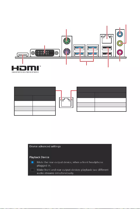
6
.
USB 3.2 Gen 1
LAN
DVI-D
USB 2.0 Type-A

7
M2_1
JTPM1
JUSB2
JUSB1
CPU_FAN1
SYS_FAN1
PCI_E1
PCI_E2
CPU_PWR1
JCI1
JCOM1
JAUD1 JFP1
JFP2
ATX_PWR1
SATA4
SATA3
SATA2
SATA1
JUSB3
JBAT1
DIMMB1
DIMMA1

8
1
3
4
6
7
8
2
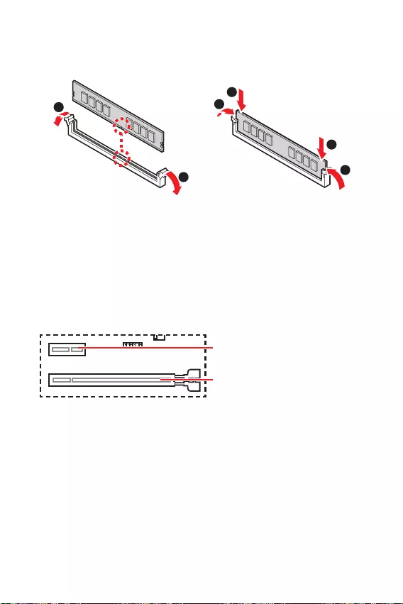
9
1
1
2
3
3
2
PCIe 4.0/ 3.0 x16 (CPU)
PCIe 3.0 x1 (PCH)

10
SATA3
SATA4
SATA1
SATA2
1
3
30º30º
2
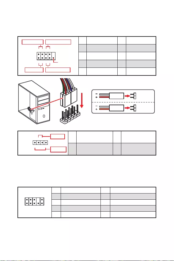
11
1
2 10
9
+
+
+— ——
—
+
Power LED
HDD LED Reset Switch
Reserved
Power Switch 1 HDD LED + 2 Power LED +
3 HDD LED — 4 Power LED —
5 Reset Switch 6 Power Switch
7 Reset Switch 8 Power Switch
9 Reserved 10 No Pin
JFP2 1
+
+—
—
Speaker
Buzzer 1 Speaker — 2 Buzzer +
3 Buzzer — 4 Speaker +
HDD LED
RESET SW
HDD LED HDD LED —
HDD LED +
POWER LED —
POWER LED +
POWER LED
JFP1
1
2 10
9
1 MIC L 2 Ground
3 MIC R 4 NC
5 Head Phone R 6 MIC Detection
7 SENSE_SEND 8 No Pin
9 Head Phone L 10 Head Phone Detection
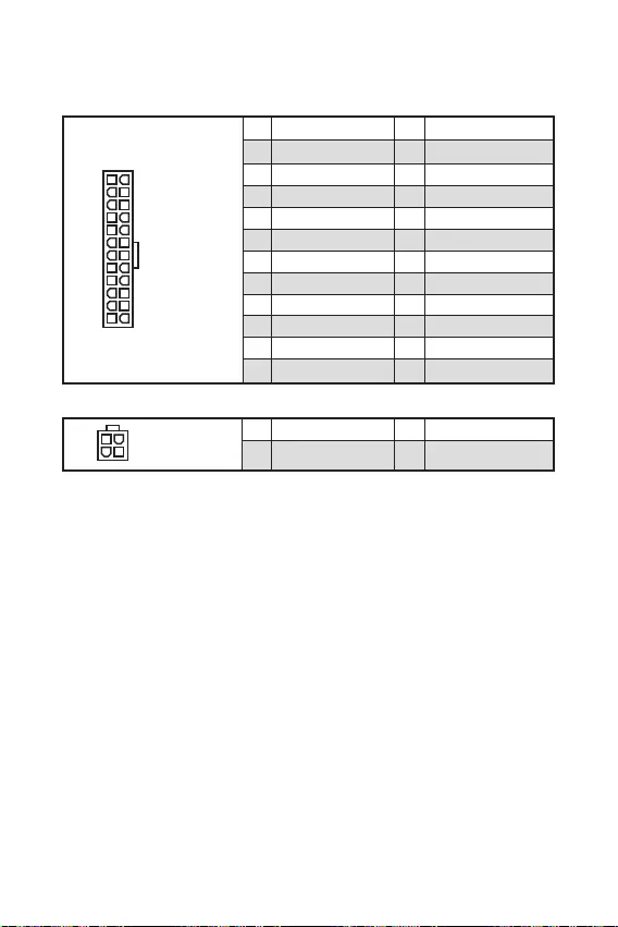
12
24
131
12
ATX_PWR1
1 +3.3V 13 +3.3V
2 +3.3V 14 -12V
3 Ground 15 Ground
4 +5V 16 PS-ON#
5 Ground 17 Ground
6 +5V 18 Ground
7 Ground 19 Ground
8 PWR OK 20 Res
9 5VSB 21 +5V
10 +12V 22 +5V
11 +12V 23 +5V
12 +3.3V 24 Ground
3
2 1
4CPU_PWR1
1 Ground 3 +12V
2 Ground 4 +12V

13
110
11
20
1 Power 11 USB2.0+
2 USB3_RX_DN 12 USB2.0-
3 USB3_RX_DP 13 Ground
4 Ground 14 USB3_TX_C_DP
5 USB3_TX_C_DN 15 USB3_TX_C_DN
6 USB3_TX_C_DP 16 Ground
7 Ground 17 USB3_RX_DP
8 USB2.0- 18 USB3_RX_DN
9 USB2.0+ 19 Power
10 NC 20 No Pin
1
2 10
9
1 VCC 2 VCC
3 USB0- 4 USB1-
5 USB0+ 6 USB1+
7 Ground 8 Ground
9 No Pin 10 NC
® SUPER CHARGER.
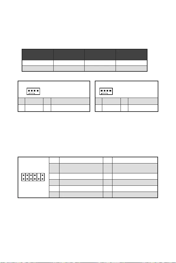
14
1
1 Ground 2 +12V
3 Sense 4 Speed Control Signal
CPU_FAN1
SYS_FAN1
1
1 Ground 2 Voltage Control
3 Sense 4 NC
1
212
11
1 SPI Power 2 SPI Chip Select
3
Master In Slave Out (SPI
Data)
4
Master In Slave In (SPI
Data)
5 Reserved 6 SPI Clock
7 Ground 8 SPI Reset
9 Reserved 10 No Pin
11 Reserved 12 Interrupt Request

.
.
.
F10
.
.
, Reset.
F10
.
1
2 10
9
1 DCD 2 SIN
3 SOUT 4 DTR
5 Ground 6 DSR
7 RTS 8 CTS
9 RI 10 No Pin

16

17
».

18
.
F1
F2
F3
F4
F6
F7
F8
F9
F10
F12
F6
.

19
BIOS.
.
Scan

20
Windows® 10.
F11
MSI Driver Disc.
.
.

1
2
3
6
…………………………………………………………………………………….6
7
………………………………………………………………………………………………………8
……………………………………………………………………………………………………9
……………………………………………………………………………….9
……………………………………………………………………………………………10
…………………………………………………………………………..10
…………………………………………………………………………….11
…………………………………………………………………………………..11
………………………………………………………………..12
………………………………………………………………………..13
……………………………………………………………………………13
………………………………………………………………….14
………………………………………………………………………………….14
……………………………………………………………………………….15
………………………………………………………………………………….15
………………………………………………………………16
………………………………………………………………………………………….16
17
……………………………………………………………………………………………………18
…………………………………………………………………………………………….18
……………………………………………………………………………………………………18
……………………………………………………………………………………………………19
20
………………………………………………………………………………………..20
…………………………………………………………………………………………………….20
…………………………………………………………………………………………………….20

2

3
DDR4 1866/ 2133/ 2400/ 2667/ 2800/ 2933/ 3000/
DDR4 2667/ 2800 /2933 /3000 /3066 /3200 /3466
B550M-A PRO PCIe 4.0/3.0*
A520M-A PRO PCIe 3.0
/**
7.1-

4
2
6 USB 2.0 (2
4
4

UEFI AMI BIOS
ACPI 6.0, SMBIOS 2.8
DRAGON CENTER
True Color
Live Update
msi.com/manual/mb/
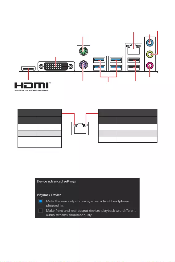
6
USB 3.2 Gen 1
(5Gbps) Type-A
LAN
DVI-D
USB 2.0 Type-A
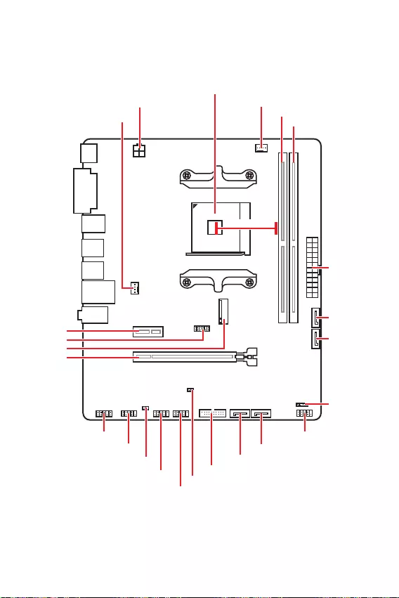
7
M2_1
JTPM1
JUSB2
JUSB1
CPU_FAN1
SYS_FAN1
PCI_E1
PCI_E2
CPU_PWR1
JCI1
JCOM1
JAUD1 JFP1
JFP2
ATX_PWR1
SATA4
SATA3
SATA2
SATA1
JUSB3
JBAT1
DIMMB1
DIMMA1

8
1
3
4
6
7
8
2
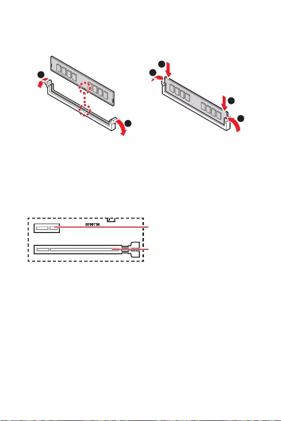
9
1
1
2
3
3
2
PCIe 4.0/ 3.0 x16 (CPU)
PCIe 3.0 x1 (PCH)
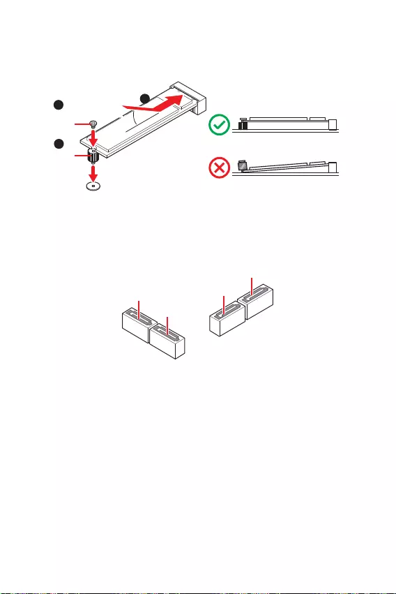
10
SATA3
SATA4
SATA1
SATA2
1
3
30º30º
2

11
1
2 10
9
+
+
+— ——
—
+
Power LED
HDD LED Reset Switch
Reserved
Power Switch 1 HDD LED + 2 Power LED +
3 HDD LED — 4 Power LED —
5 Reset Switch 6 Power Switch
7 Reset Switch 8 Power Switch
9 Reserved 10 No Pin
JFP2 1
+
+—
—
Speaker
Buzzer 1 Speaker — 2 Buzzer +
3 Buzzer — 4 Speaker +
HDD LED
RESET SW
HDD LED HDD LED —
HDD LED +
POWER LED —
POWER LED +
POWER LED
JFP1
1
2 10
9
1 MIC L 2 Ground
3 MIC R 4 NC
5 Head Phone R 6 MIC Detection
7 SENSE_SEND 8 No Pin
9 Head Phone L 10 Head Phone Detection

12
24
131
12
ATX_PWR1
1 +3.3V 13 +3.3V
2 +3.3V 14 -12V
3 Ground 15 Ground
4 +5V 16 PS-ON#
5 Ground 17 Ground
6 +5V 18 Ground
7 Ground 19 Ground
8 PWR OK 20 Res
9 5VSB 21 +5V
10 +12V 22 +5V
11 +12V 23 +5V
12 +3.3V 24 Ground
3
2 1
4CPU_PWR1
1 Ground 3 +12V
2 Ground 4 +12V
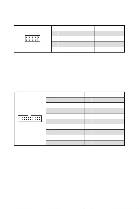
13
110
11
20
1 Power 11 USB2.0+
2 USB3_RX_DN 12 USB2.0-
3 USB3_RX_DP 13 Ground
4 Ground 14 USB3_TX_C_DP
5 USB3_TX_C_DN 15 USB3_TX_C_DN
6 USB3_TX_C_DP 16 Ground
7 Ground 17 USB3_RX_DP
8 USB2.0- 18 USB3_RX_DN
9 USB2.0+ 19 Power
10 NC 20 No Pin
1
2 10
9
1 VCC 2 VCC
3 USB0- 4 USB1-
5 USB0+ 6 USB1+
7 Ground 8 Ground
9 No Pin 10 NC

14
1
1 Ground 2 +12V
3 Sense 4 Speed Control Signal
CPU_FAN1 1A 12W
SYS_FAN1 1A 12W
1
1 Ground 2 Voltage Control
3 Sense 4 NC
1
212
11
1 SPI Power 2 SPI Chip Select
3
Master In Slave Out (SPI
Data)
4
Master In Slave In (SPI
Data)
5 Reserved 6 SPI Clock
7 Ground 8 SPI Reset
9 Reserved 10 No Pin
11 Reserved 12 Interrupt Request

F10
Reset
F10
1
2 10
9
1 DCD 2 SIN
3 SOUT 4 DTR
5 Ground 6 DSR
7 RTS 8 CTS
9 RI 10 No Pin

16
BIOS

17

18
F1
F2
F3
F4
F6
F7
F8
F9
F10
F12:
F6

19

20
Windows® 10
F11
Windows® 10
Windows® 10
Windows® 10
MSI®

1
2
3
6
………………………………………………………………………………6
7
………………………………………………………………………………………………………8
……………………………………………………………………………………………………9
……………………………………………………………………………….9
……………………………………………………………………………………………10
…………………………………………………………………………..10
…………………………………………………………………………….11
…………………………………………………………………………………..11
………………………………………………………………..12
………………………………………………………………………..13
……………………………………………………………………………13
……………………………………………………………14
………………………………………………………………………………….14
………………………………………………………………………………………15
……………………………………………………………………………………..15
………………………………………………………16
………………………………………………………………………………………….16
17
……………………………………………………………………………………………………18
…………………………………………………………………………………………….18
……………………………………………………………………………………………………18
……………………………………………………………………………………………………19
20
® 10 ………………………………………………………………………………………..20
………………………………………………………………………………………………20
………………………………………………………………………………………………20

2

3
B550M-A PRO PCIe 4.0/3.0*
A520M-A PRO PCIe 3.0
/**

4
2 USB 3.2 Gen 1 5Gbps USB 3.2 Gen
1 5Gbps
6 USB 2.0 (2
USB 2.0 )
4 USB 3.2 Gen 1 5Gbps Type-A
mATX
UEFI AMI BIOS
ACPI 6.0, SMBIOS 2.8
DRAGON CENTER
CPU-Z MSI GAMING
Norton™ Internet Security Solution
User Scenario
Hardware Monitor
True Color
Live Update
Speed Up
Smart Tool
Super Charger
msi.com/manual/mb/
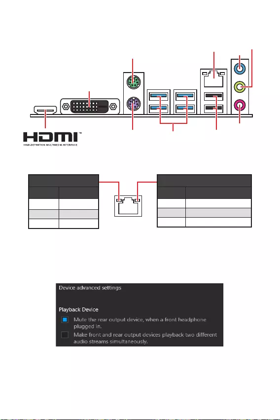
6
USB 3.2 Gen 1
(5Gbps) Type-A
DVI-D
USB 2.0 Type-A

7
M2_1
JTPM1
JUSB2
JUSB1
CPU_FAN1
SYS_FAN1
PCI_E1
PCI_E2
CPU_PWR1
JCI1
JCOM1
JAUD1 JFP1
JFP2
ATX_PWR1
SATA4
SATA3
SATA2
SATA1
JUSB3
JBAT1
DIMMB1
DIMMA1
50.89mm*
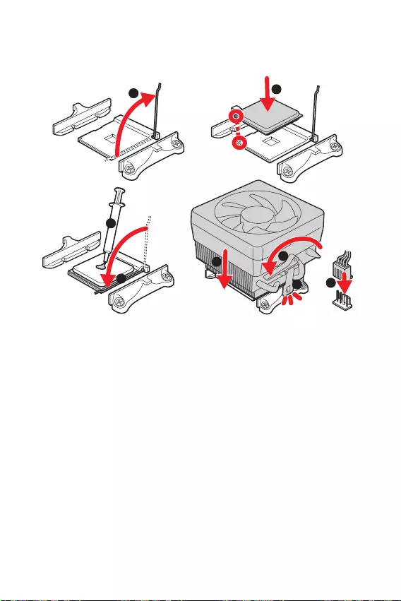
8
1
3
4
6
7
8
2
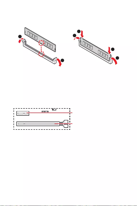
9
1
1
2
3
3
2
PCIe 4.0/ 3.0 x16 (CPU)
PCIe 3.0 x1 (PCH)

10
SATA3
SATA4
SATA1
SATA2
1
3
30º30º
2
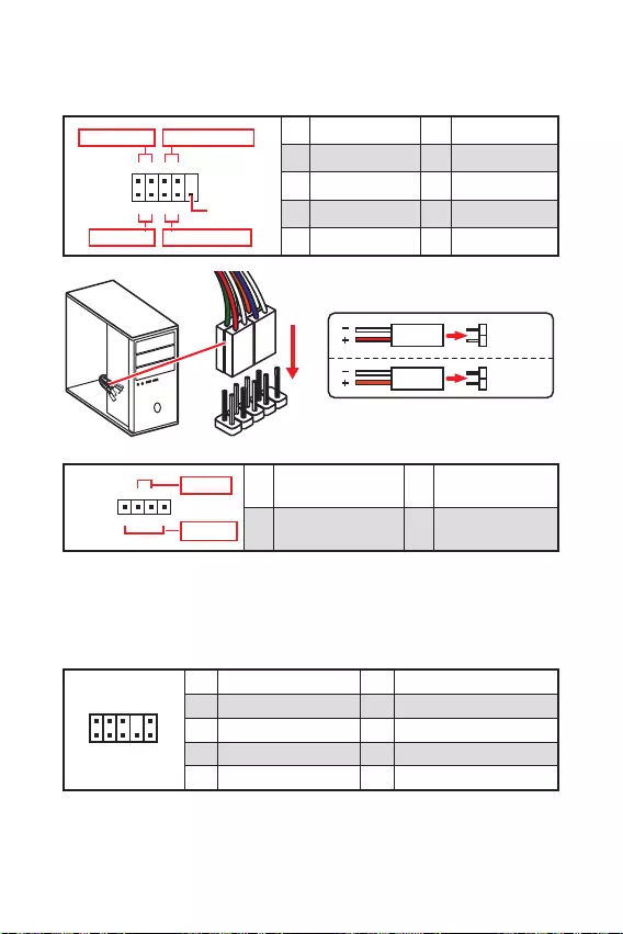
11
1
2 10
9
+
+
+— ——
—
+
Power LED
HDD LED Reset Switch
Reserved
Power Switch 1 HDD LED + 2 Power LED +
3 HDD LED — 4 Power LED —
5 Reset Switch 6 Power Switch
7 Reset Switch 8 Power Switch
9 Reserved 10 No Pin
JFP2 1
+
+—
—
Speaker
Buzzer 1 Speaker — 2 Buzzer +
3 Buzzer — 4 Speaker +
HDD LED
RESET SW
HDD LED HDD LED —
HDD LED +
POWER LED —
POWER LED +
POWER LED
JFP1
1
2 10
9
1 MIC L 2 Ground
3 MIC R 4 NC
5 Head Phone R 6 MIC Detection
7 SENSE_SEND 8 No Pin
9 Head Phone L 10 Head Phone Detection

12
24
131
12
ATX_PWR1
1 +3.3V 13 +3.3V
2 +3.3V 14 -12V
3 Ground 15 Ground
4 +5V 16 PS-ON#
5 Ground 17 Ground
6 +5V 18 Ground
7 Ground 19 Ground
8 PWR OK 20 Res
9 5VSB 21 +5V
10 +12V 22 +5V
11 +12V 23 +5V
12 +3.3V 24 Ground
3
2 1
4CPU_PWR1
1 Ground 3 +12V
2 Ground 4 +12V

13
110
11
20
1 Power 11 USB2.0+
2 USB3_RX_DN 12 USB2.0-
3 USB3_RX_DP 13 Ground
4 Ground 14 USB3_TX_C_DP
5 USB3_TX_C_DN 15 USB3_TX_C_DN
6 USB3_TX_C_DP 16 Ground
7 Ground 17 USB3_RX_DP
8 USB2.0- 18 USB3_RX_DN
9 USB2.0+ 19 Power
10 NC 20 No Pin
1
2 10
9
1 VCC 2 VCC
3 USB0- 4 USB1-
5 USB0+ 6 USB1+
7 Ground 8 Ground
9 No Pin 10 NC

14
1
1 Ground 2 +12V
3 Sense 4 Speed Control Signal
CPU_FAN1 1A 12W
SYS_FAN1 1A 12W
1
1 Ground 2 Voltage Control
3 Sense 4 NC
1
212
11
1 SPI Power 2 SPI Chip Select
3
Master In Slave Out (SPI
Data)
4
Master In Slave In (SPI
Data)
5 Reserved 6 SPI Clock
7 Ground 8 SPI Reset
9 Reserved 10 No Pin
11 Reserved 12 Interrupt Request

F10
Reset
1
2 10
9
1 DCD 2 SIN
3 SOUT 4 DTR
5 Ground 6 DSR
7 RTS 8 CTS
9 RI 10 No Pin

16
BIOS
—

17

18
F1:
F2:
F3:
F4:
:
F6:
F7:
F8:
F9:
F10: *
F12:
:
F6

19

20
®
®
®

1
2
3
6
…………………………………………………………………………………….6
7
………………………………………………………………………………………………….8
………………………………………………………………………………………………..9
…………………………………………………………………………..9
………………………………………………………………………………………..10
………………………………………………………………….10
……………………………………………………………11
……………………………………………………………..11
……………………………………………………….12
………………………………………………………………..13
……………………………………………………………………13
……………………………………………………….14
………………………………………………………………….14
……………………………………………………………….15
………………………………………………………………….15
……………………………………………………16
EZ Debug LED ……………………………………………………………………………………………..16
17
…………………………………………………………………………………………………18
………………………………………………………………………….18
…………………………………………………………………………………………….18
……………………………………………………………………………….19
20
Windows® …………………………………………………………………………..20
………………………………………………………………………………20
………………………………………………………………………….20

2

3
3000/ 3066/ 3200
/3066 /3200 /3466 /3600/ 3733 /3866 /4000 /4133 /4266
/**

4
9.3 in. x 7.9 in. (23.6 cm x 20 cm)
UEFI AMI BIOS
ACPI 6.0, SMBIOS 2.8
DRAGON CENTER
CPU-Z MSI GAMING
Google Chrome™, Google Toolbar, Google Drive
Norton™ Internet Security Solution
User Scenario
Hardware Monitor
True Color
Live Update
Speed Up
Smart Tool
Super Charger
download.msi.com/manual/

6
Off
Off 10 Mbps
100 Mbps
1 Gbps
USB 3.2 Gen 1
(5Gbps) Type-A
LAN
DVI-D
USB 2.0 Type-A

7
M2_1
JTPM1
JUSB2
JUSB1
CPU_FAN1
SYS_FAN1
PCI_E1
PCI_E2
CPU_PWR1
JCI1
JCOM1
JAUD1 JFP1
JFP2
ATX_PWR1
SATA4
SATA3
SATA2
SATA1
JUSB3
JBAT1
DIMMB1
DIMMA1
50.89mm*

8
1
3
4
6
7
8
2

9
1
1
2
3
3
2
PCIe 4.0/ 3.0 x16 (CPU)
PCIe 3.0 x1 (PCH)

10
SATA3
SATA4
SATA1
SATA2
1
3
30º30º
2

11
1
2 10
9
+
+
+— ——
—
+
Power LED
HDD LED Reset Switch
Reserved
Power Switch 1 HDD LED + 2 Power LED +
3 HDD LED — 4 Power LED —
5 Reset Switch 6 Power Switch
7 Reset Switch 8 Power Switch
9 Reserved 10 No Pin
JFP2 1
+
+—
—
Speaker
Buzzer 1 Speaker — 2 Buzzer +
3 Buzzer — 4 Speaker +
HDD LED
RESET SW
HDD LED HDD LED —
HDD LED +
POWER LED —
POWER LED +
POWER LED
JFP1
1
2 10
9
1 MIC L 2 Ground
3 MIC R 4 NC
5 Head Phone R 6 MIC Detection
7 SENSE_SEND 8 No Pin
9 Head Phone L 10 Head Phone Detection
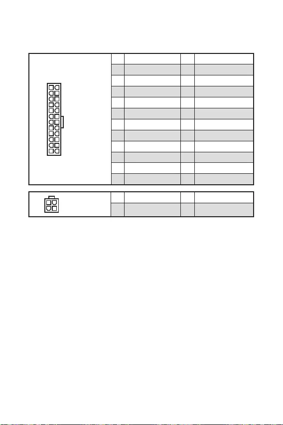
12
24
131
12
ATX_PWR1
1 +3.3V 13 +3.3V
2 +3.3V 14 -12V
3 Ground 15 Ground
4 +5V 16 PS-ON#
5 Ground 17 Ground
6 +5V 18 Ground
7 Ground 19 Ground
8 PWR OK 20 Res
9 5VSB 21 +5V
10 +12V 22 +5V
11 +12V 23 +5V
12 +3.3V 24 Ground
3
2 1
4CPU_PWR1
1 Ground 3 +12V
2 Ground 4 +12V

13
110
11
20
1 Power 11 USB2.0+
2 USB3_RX_DN 12 USB2.0-
3 USB3_RX_DP 13 Ground
4 Ground 14 USB3_TX_C_DP
5 USB3_TX_C_DN 15 USB3_TX_C_DN
6 USB3_TX_C_DP 16 Ground
7 Ground 17 USB3_RX_DP
8 USB2.0- 18 USB3_RX_DN
9 USB2.0+ 19 Power
10 NC 20 No Pin
1
2 10
9
1 VCC 2 VCC
3 USB0- 4 USB1-
5 USB0+ 6 USB1+
7 Ground 8 Ground
9 No Pin 10 NC
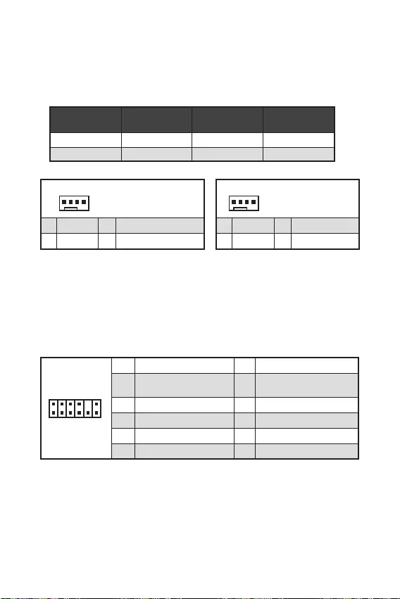
14
1
1 Ground 2 +12V
3 Sense 4 Speed Control Signal
CPU_FAN1 1A 12W
SYS_FAN1 1A 12W
1
1 Ground 2 Voltage Control
3 Sense 4 NC
1
212
11
1 SPI Power 2 SPI Chip Select
3
Master In Slave Out (SPI
Data)
4
Master In Slave In (SPI
Data)
5 Reserved 6 SPI Clock
7 Ground 8 SPI Reset
9 Reserved 10 No Pin
11 Reserved 12 Interrupt Request

F10
Reset
F10
1
2 10
9
1 DCD 2 SIN
3 SOUT 4 DTR
5 Ground 6 DSR
7 RTS 8 CTS
9 RI 10 No Pin
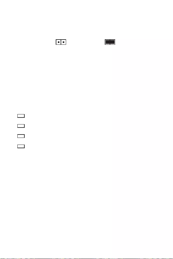
16

17

18
F1:
F2:
F3:
F4:
:
F6: O
F7:
F8:
F9:
F10: *
F12:
F6

19

20
Windows®
F11
®
Windows®
MSI®
Note: This equipment has been tested and
found to comply with the limits for a Class B
digital device, pursuant to part 15 of the FCC
Rules. These limits are designed to provide
reasonable protection against harmful
interference in a residential installation.
This equipment generates, uses and can
radiate radio frequency energy and, if not
installed and used in accordance with the
instructions, may cause harmful interference
to radio communications. However, there is
no guarantee that interference will not occur
in a particular installation. If this equipment
does cause harmful interference to radio or
television reception, which can be determined
by turning the equipment off and on, the user is
encouraged to try to correct the interference by
one or more of the following measures:
Reorient or relocate the receiving antenna.
Increase the separation between the
equipment and receiver.
Connect the equipment into an outlet on
a circuit different from that to which the
receiver is connected.
Consult the dealer or an experienced radio/TV
technician for help.
Caution: Changes or modifications not
expressly approved by the party responsible for
compliance could void the user’s authority to
operate the equipment.
Tested to comply with FCC standards
FOR HOME OR OFFICE USE
This device complies with part 15 of the FCC
Rules. Operation is subject to the following two
conditions:
(1) This device may not cause harmful
interference, and (2) this device must accept any
interference received, including interference
that may cause undesired operation.
Products bearing the CE marking
comply with one or more of the
following EU Directives as may be
applicable:
RED 2014/53/EU; Low Voltage Directive 2014/35/
EU; EMC Directive 2014/30/EU; RoHS Directive
2011/65/EU.
Compliance with these directives is assessed
using applicable European Harmonized
Standards.
The point of contact for regulatory matters
is MSI,
MSI-NL Eindhoven 5706 5692 ER Son.
European Union:
Batteries, battery packs, and
accumulators should not be
disposed of as unsorted household
waste. Please use the public
collection system to return, recycle,
or treat them in compliance with the
local regulations.
Taiwan:
For better environmental protection,
waste batteries should be collected
separately for recycling or special
disposal.
California, USA:
The button cell battery may contain
perchlorate material and requires
special handling when recycled or
disposed of in California.
For further information please visit:
http://www.dtsc.ca.gov/hazardouswaste/
perchlorate/
CAUTION: There is a risk of explosion, if battery
is incorrectly replaced.
Replace only with the same or equivalent type
recommended by the manufacturer.
In compliance with chemical substances
regulations, such as the EU REACH Regulation
(Regulation EC No. 1907/2006 of the European
Parliament and the Council), MSI provides
the information of chemical substances in
products at:
https://storage-asset.msi.com/html/popup/csr/
evmtprtt_pcm.html

To protect the global environment
and as an environmentalist, MSI
must remind you that…
Under the European Union (“EU”)
Directive on Waste Electrical and
Electronic Equipment, Directive
2002/96/EC, which takes effect on August 13,
2005, products of “electrical and electronic
equipment” cannot be discarded as municipal
wastes anymore, and manufacturers of covered
electronic equipment will be obligated to take
back such products at the end of their useful
life. MSI will comply with the product take back
requirements at the end of life of MSI-branded
products that are sold into the EU. You can
return these products to local collection points.
Hinweis von MSI zur Erhaltung und Schutz
unserer Umwelt
Gemäß der Richtlinie 2002/96/EG über
Elektro- und Elektronik-Altgeräte dürfen
Elektro- und Elektronik-Altgeräte nicht
mehr als kommunale Abfälle entsorgt
werden. MSI hat europaweit verschiedene
Sammel- und Recyclingunternehmen
beauftragt, die in die Europäische Union
in Verkehr gebrachten Produkte, am Ende
seines Lebenszyklus zurückzunehmen. Bitte
entsorgen Sie dieses Produkt zum gegebenen
Zeitpunkt ausschliesslich an einer lokalen
Altgerätesammelstelle in Ihrer Nähe.
En tant qu’écologiste et afin de protéger
l’environnement, MSI tient à rappeler ceci…
Au sujet de la directive européenne (EU) relative
aux déchets des équipement électriques et
électroniques, directive 2002/96/EC, prenant
effet le 13 août 2005, que les produits
électriques et électroniques ne peuvent être
déposés dans les décharges ou tout simplement
mis à la poubelle. Les fabricants de ces
équipements seront obligés de récupérer
certains produits en fin de vie. MSI prendra en
compte cette exigence relative au retour des
produits en fin de vie au sein de la communauté
européenne. Par conséquent vous pouvez
retourner localement ces matériels dans les
points de collecte.
MSI como empresa comprometida con la
protección del medio ambiente, recomienda:
Bajo la directiva 2002/96/EC de la Unión
Europea en materia de desechos y/o equipos
electrónicos, con fecha de rigor desde el 13 de
agosto de 2005, los productos clasificados como
“eléctricos y equipos electrónicos” no pueden
ser depositados en los contenedores habituales
de su municipio, los fabricantes de equipos
electrónicos, están obligados a hacerse cargo
de dichos productos al termino de su período de
vida. MSI estará comprometido con los términos
de recogida de sus productos vendidos en la
Unión Europea al final de su periodo de vida.
Usted debe depositar estos productos en el
punto limpio establecido por el ayuntamiento
de su localidad o entregar a una empresa
autorizada para la recogida de estos residuos.
Om het milieu te beschermen, wil MSI u eraan
herinneren dat….
De richtlijn van de Europese Unie (EU) met
betrekking tot Vervuiling van Electrische en
Electronische producten (2002/96/EC), die op
13 Augustus 2005 in zal gaan kunnen niet meer
beschouwd worden als vervuiling. Fabrikanten
van dit soort producten worden verplicht om
producten retour te nemen aan het eind van
hun levenscyclus. MSI zal overeenkomstig de
richtlijn handelen voor de producten die de
merknaam MSI dragen en verkocht zijn in de EU.
Deze goederen kunnen geretourneerd worden
op lokale inzamelingspunten.
mora da vas podesti da…
2002/96/EC, koja stupa na snagu od 13. Avgusta
2005, proizvodi koji spadaju pod “elektronsku i
proizvoda kojima je istekao vek trajanja, koji
imaju MSI oznaku i koji su prodati u EU. Ove
za prikupljanje.

elektronicznych (Dyrektywa 2002/96/EC), która
(sprzedawane na terenie Unii Europejskiej)
zbiorczych.
itibaren geçerli olmak üzere, elektrikli ve
sonra ürünleri geri toplamakla yükümlü
EC platné od 13. srpna 2005 je zakázáno
likvidovat “elektrické a elektronické výrobky”
Annak érdekében, hogy környezetünket
az MSI emlékezteti Önt, hogy …
Az Európai Unió („EU”) 2005. augusztus 13-án
berendezések hulladékairól szóló 2002/96/
EK irányelve szerint az elektromos és
elektronikus berendezések többé nem
elektronikus berendezések gyártói kötelessé
válnak az ilyen termékek visszavételére
azok hasznos élettartama végén. Az MSI
betartja a termékvisszavétellel kapcsolatos
követelményeket az MSI márkanév alatt az EU-n
belül értékesített termékek esetében, azok
élettartamának végén. Az ilyen termékeket a
Per proteggere l’ambiente, MSI, da sempre
amica della natura, ti ricorda che….
In base alla Direttiva dell’Unione Europea
(EU) sullo Smaltimento dei Materiali Elettrici
ed Elettronici, Direttiva 2002/96/EC in vigore
dal 13 Agosto 2005, prodotti appartenenti alla
categoria dei Materiali Elettrici ed Elettronici
non possono più essere eliminati come rifiuti
municipali: i produttori di detti materiali saranno
obbligati a ritirare ogni prodotto alla fine del
suo ciclo di vita. MSI si adeguerà a tale Direttiva
ritirando tutti i prodotti marchiati MSI che sono
stati venduti all’interno dell’Unione Europea alla
fine del loro ciclo di vita. È possibile portare i
prodotti nel più vicino punto di raccolta
https://storage-asset.msi.com/html/popup/csr/
cemm_jp.html
This product complies with the “India
E-waste (Management and Handling) Rule
2011” and prohibits use of lead, mercury,
hexavalent chromium, polybrominated
biphenyls or polybrominated diphenyl ethers
in concentrations exceeding 0.1 weight % and
0.01 weight % for cadmium, except for the
exemptions set in Schedule 2 of the Rule.
Uygundur
The product has been designed
to enable proper reuse of parts
and recycling and should not be
thrown away at its end of life.
Users should contact the local
authorized point of collection for recycling
and disposing of their end-of-life products.
Visit the MSI website and locate a nearby
distributor for further recycling information.
Users may also reach us at gpcontdev@msi.
com for information regarding proper Disposal,
Take-back, Recycling, and Disassembly of MSI
products.
Micro-Star Int’l Co.,Ltd.
Copyright © 2020 All rights reserved.
The MSI logo used is a registered trademark of
Micro-Star Int’l Co., Ltd. All other marks and
names mentioned may be trademarks of their
respective owners. No warranty as to accuracy
or completeness is expressed or implied. MSI
reserves the right to make changes to this
document without prior notice.
If a problem arises with your system and no
solution can be obtained from the user guide,
please contact your place of purchase or
local distributor. Alternatively, please try the
following help resources for further guidance.
Visit the MSI website for technical guide,
BIOS updates, driver updates, and other
information: http://www.msi.com
Register your product at: http://register.
msi.com
Version 1.0, 2020/08, First release.
(Pb)
(Hg)
(Cd)
(Cr(VI))
(PBB)
(PBDE)
(Pb)
(Hg)
(Cd)
(Cr+6)
(PBB)
(PBDE)
MSI
Loading…
A
- A10M-472CZ
- A10M-479RU
- A10M-615
- A10M-669
- A10RAS-079P
- A10RAS-083CZ
- A10RAS-084CZ
- A10RAS-095
- A10RAS-284
- A10RAS-400
- A10RB-015RU
- A10RB-027
- A10RB-035CZ
- A10RB-638
- A10SC-009
- A10SC-010
- A10SC-012
- A10SC-014
- A10SC-031CZ
- A10SC-078CZ
- A10SD-415
- A10SFS-010
- A11M-013
- A11SB-014
- A11SCS-224
- A11SCS-225
- A11SCST-056
- A11SDK-067
- A11SDK-085
- A320M-A Pro2
- A320M-A Pro-M22
- A320M-A Pro Max2
- A320M gaming pro
- A320MPRO-VDH
- A320M PRO-VD PLUS
- A320M PRO-VD-S2
- A320M PRO-VHL
- A320M PRO-VH PLUS2
- A3DD-219XUA
- A3DDK-027CZ
- A4DCR-061CZ
- A4DDR-007
- A4DDR-016
- A4DDR-019
- A4DDR-022CZ
- A4DDR-039
- A4DDR-073
- A520M-A Pro2
- A520M Pro2
- A520M Pro-C DASH2
- A520M Vector WIFI
- A55-G41 PC Mate2
- A55M-E332
- A55M-E35
- A55M-E45 V2
- A55M-P33
- A55M-P35
- A58-G41 PC Mate
- A6200
- A6200-066 RU
- A68HI2
- A68HI AC2
- A68hm
- A68hm-e33
- A68HM-E33 V23
- A75A-G352
- A75A-G452
- A75A-G553
- A75IA-E53
- A75MA-E35
- A75MA-G552
- A75MA-P352
- A78-G41 PC Mate2
- A78I2
- A78I AC2
- A78I AC V2
- A78M-E35
- A78M-E45
- A78M-E45 V2
- A88X-G41
- A88X-G41 PC Mate2
- A88X-G43
- A88X-G45
- A88X-G45 GAMING2
- A88XI3
- A88XI AC2
- A88XI AC V2
- A88XI V2
- A88XM
- A88XM-E35
- A88XM-E45 V2
- A88XM GAMING
- A9SD-032
- A9SD-034RU
- A9SD-067RU
- A9SE-033RU
- A9SE-066RU
- Adora20
- Adora22
- Adora243
Loading…
Loading…
Nothing found
A520M-A Pro
Service Manual
1 pgs1.04 Mb1
User Manual
164 pgs5.6 Mb2
Table of contents
Loading…
…
MSI User Manual
Download
Specifications and Main Features
Frequently Asked Questions
User Manual


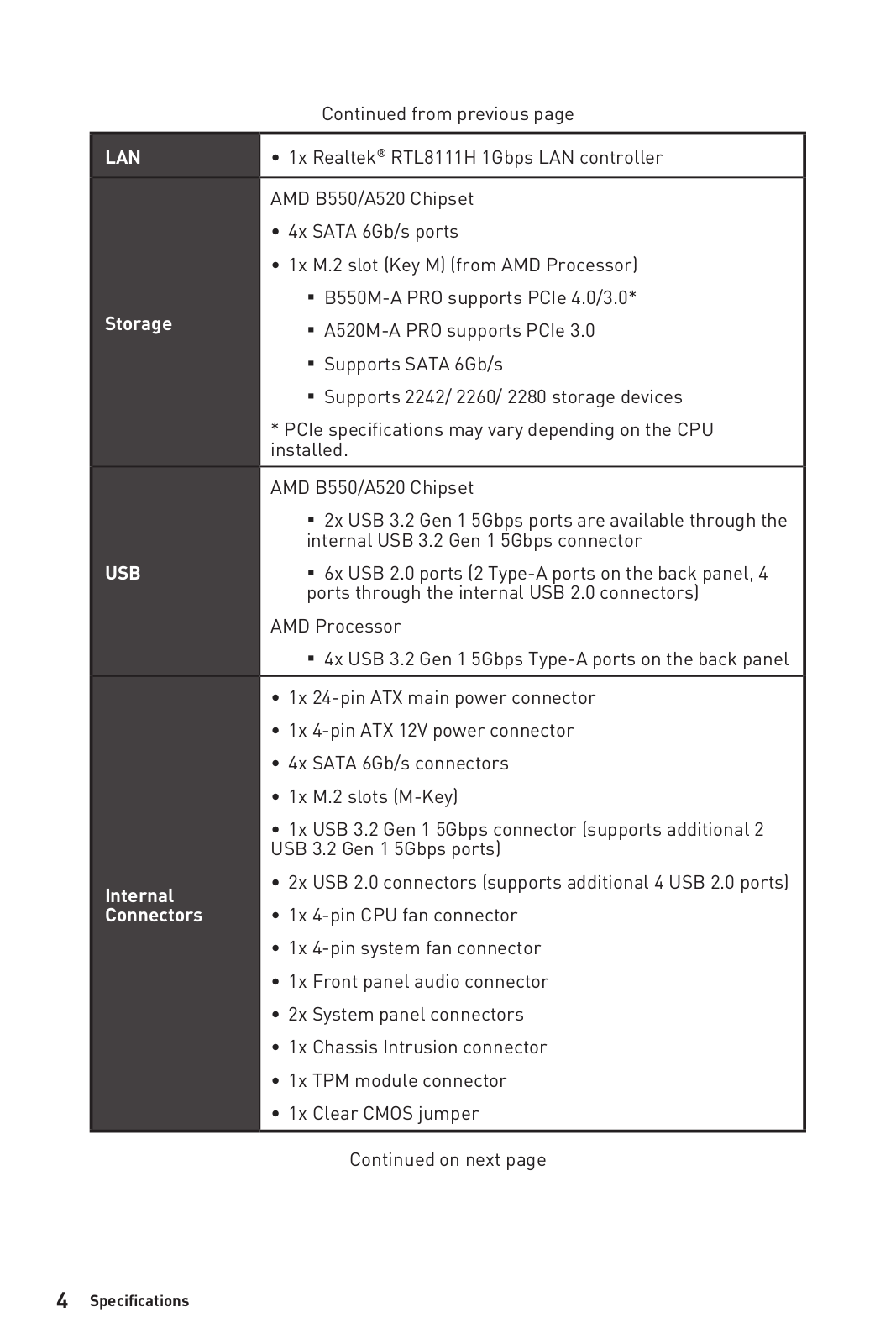
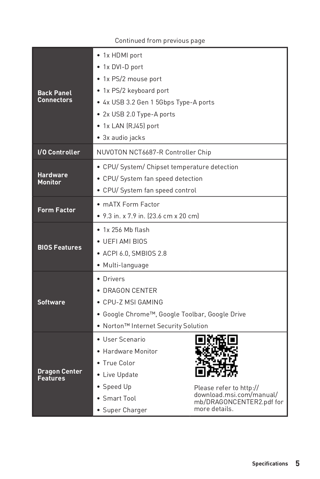
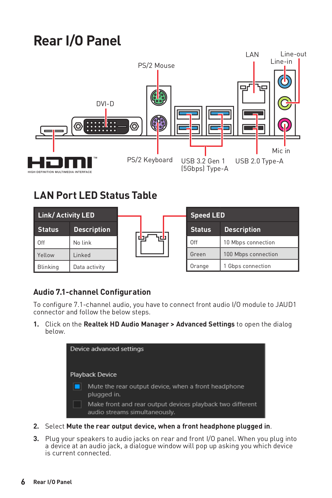


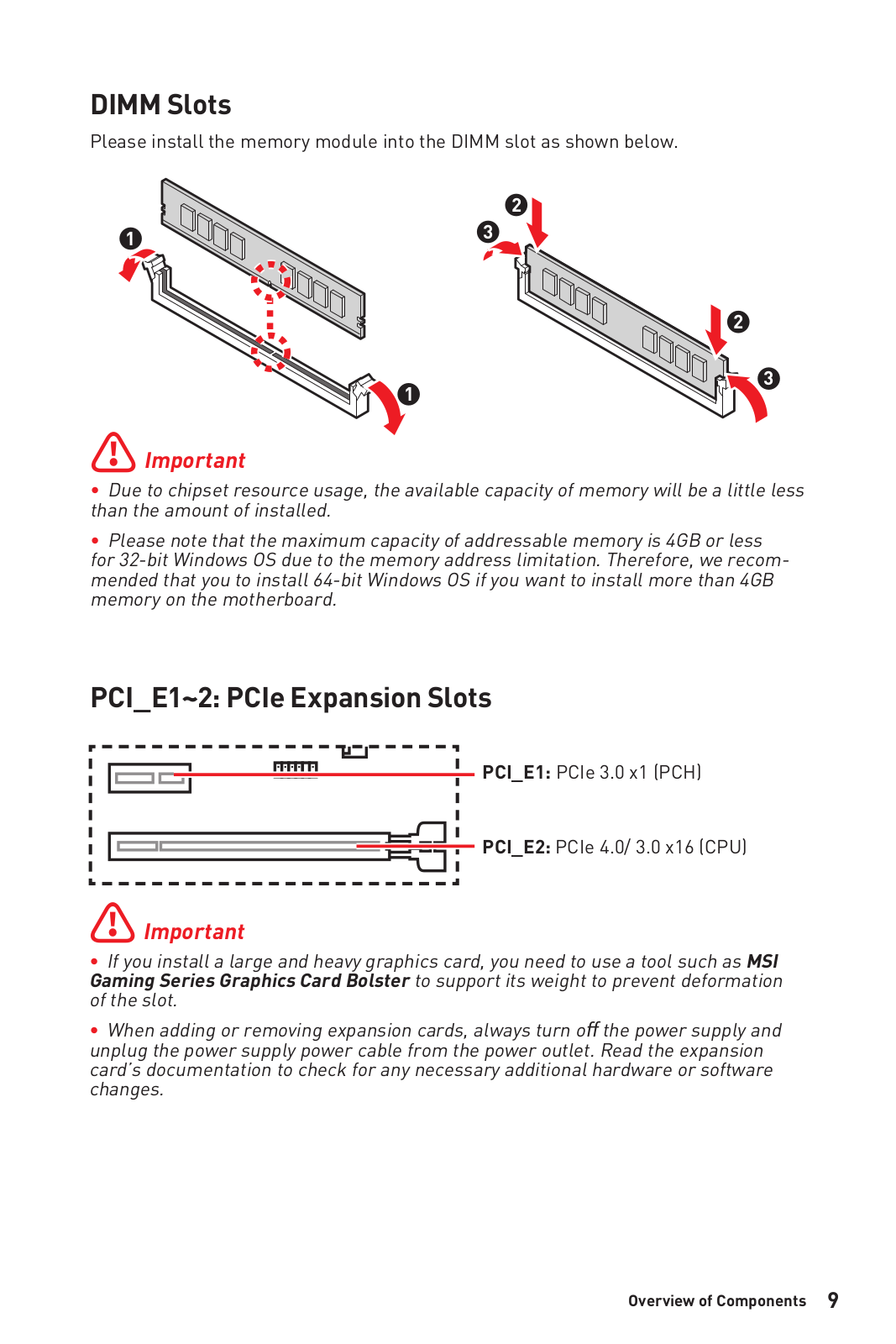

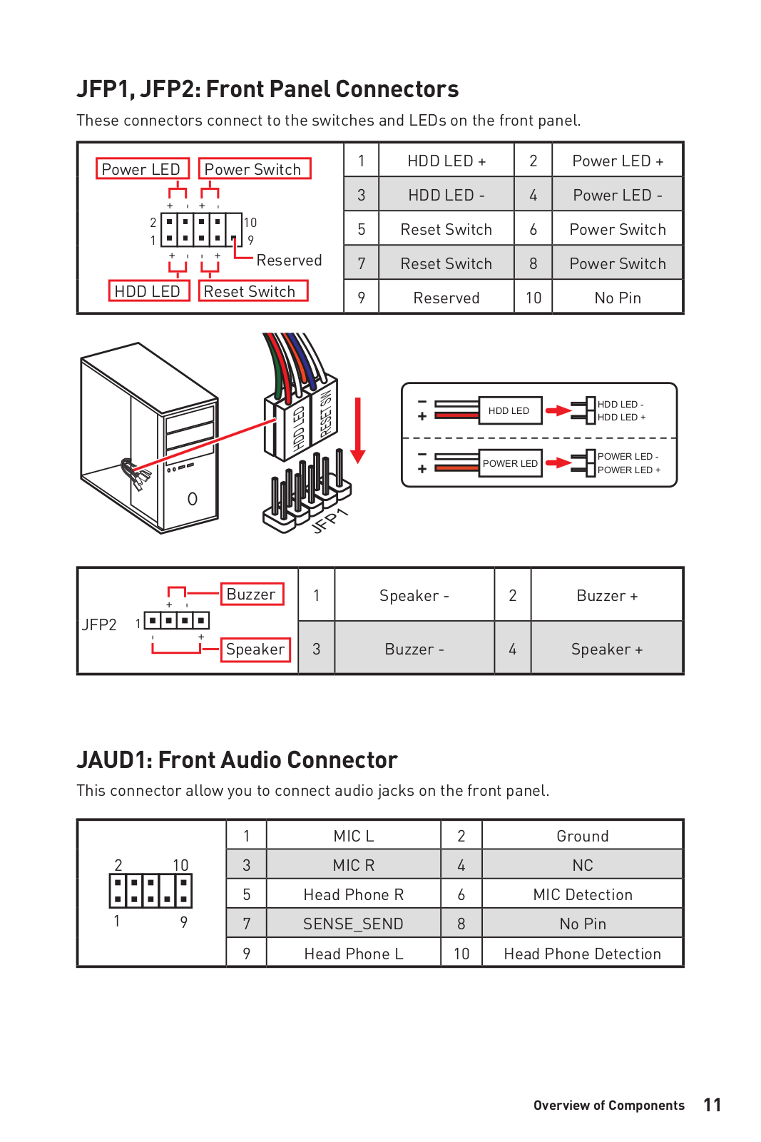
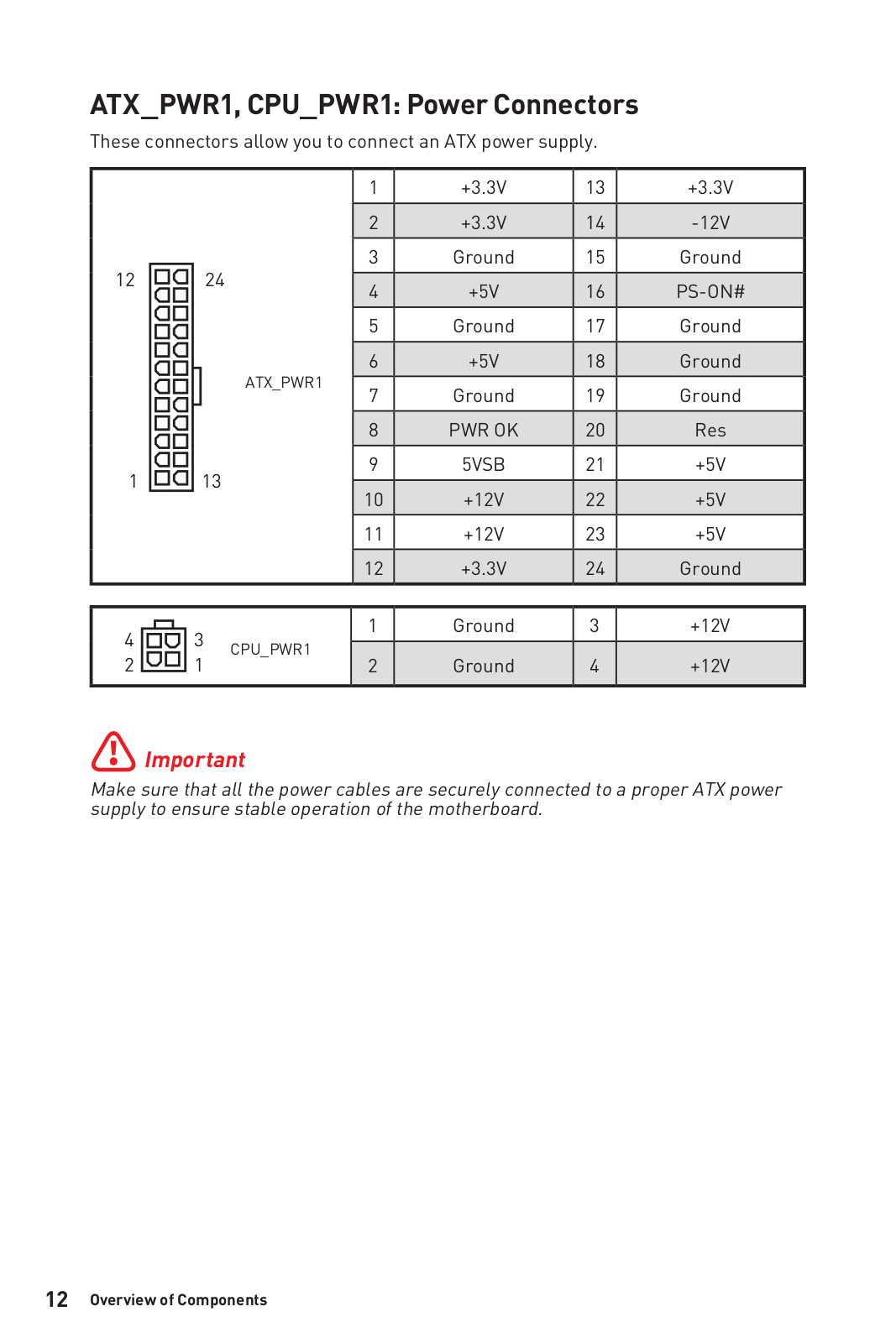
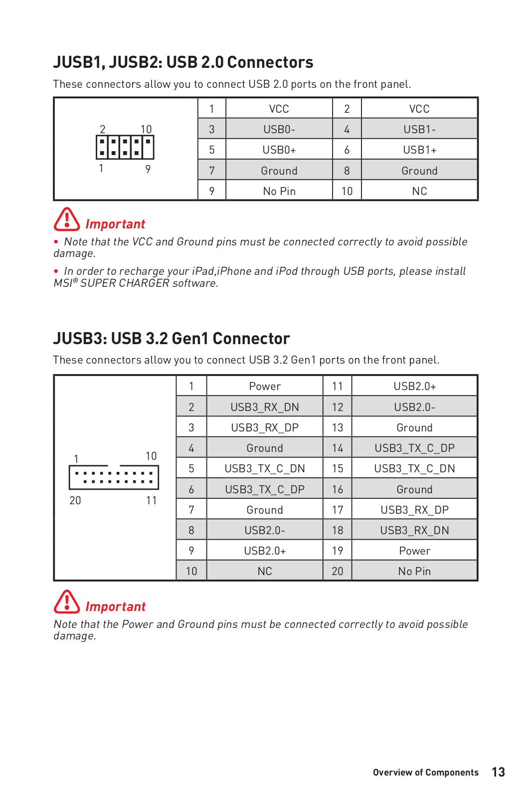

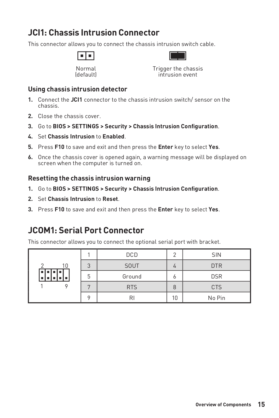

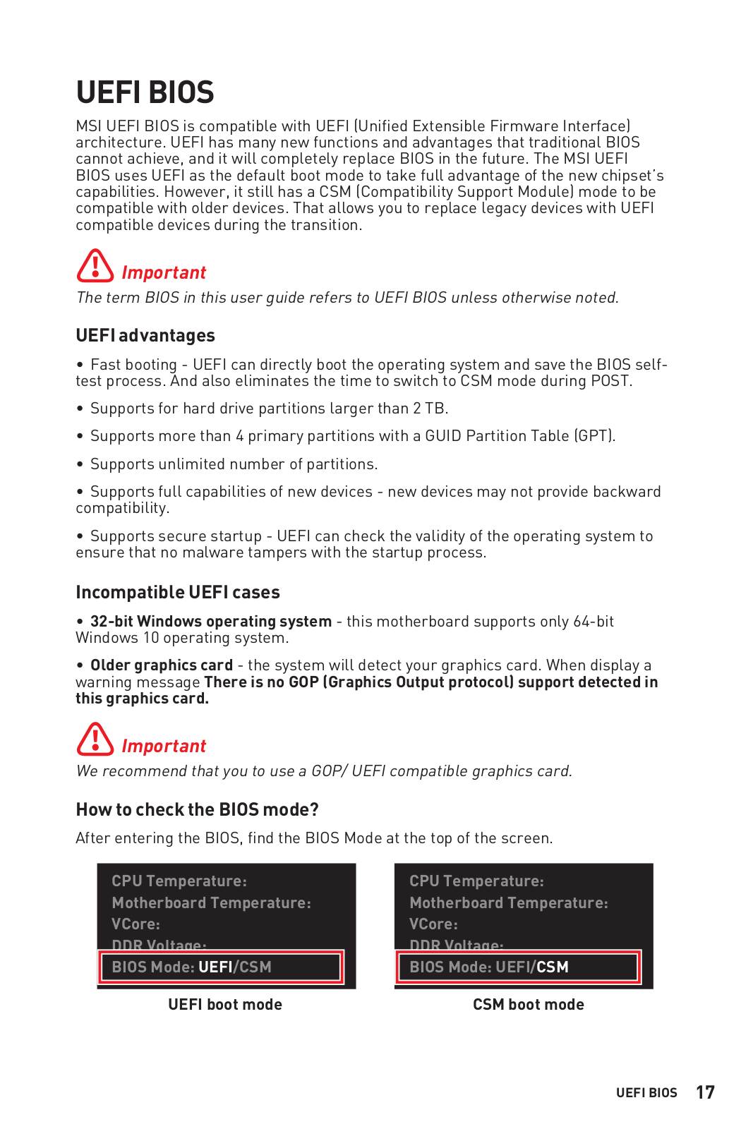


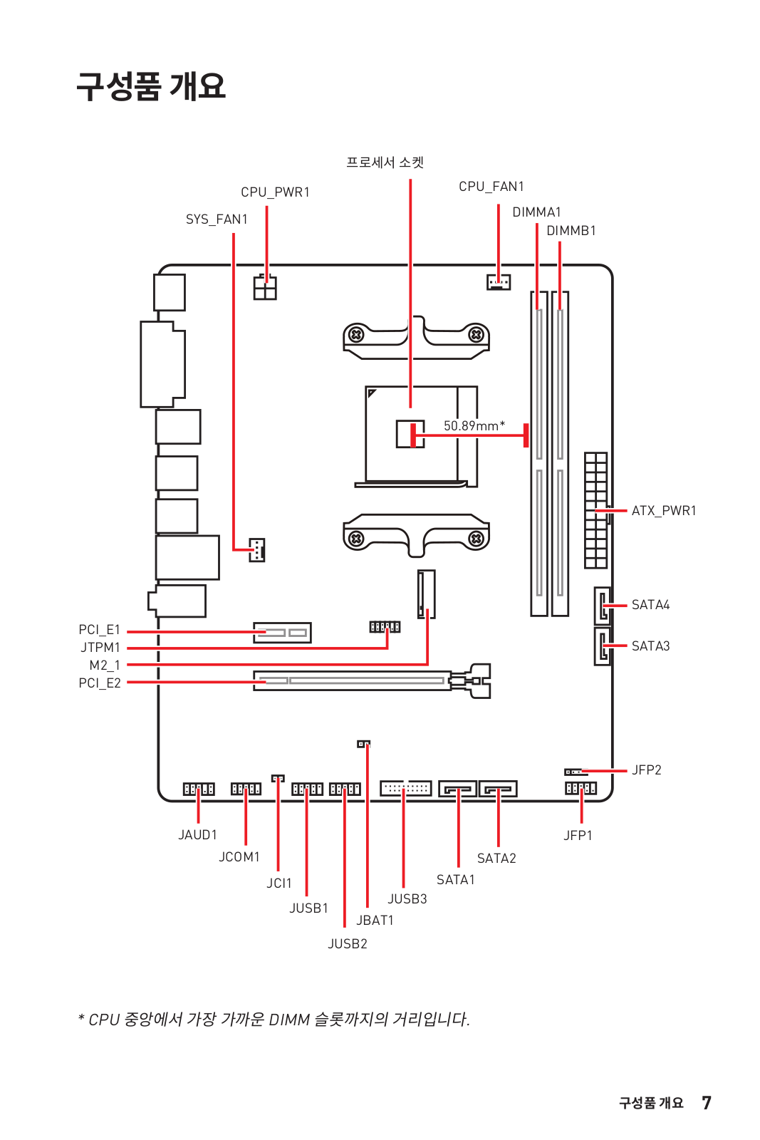
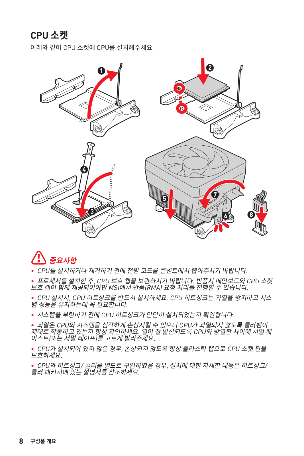
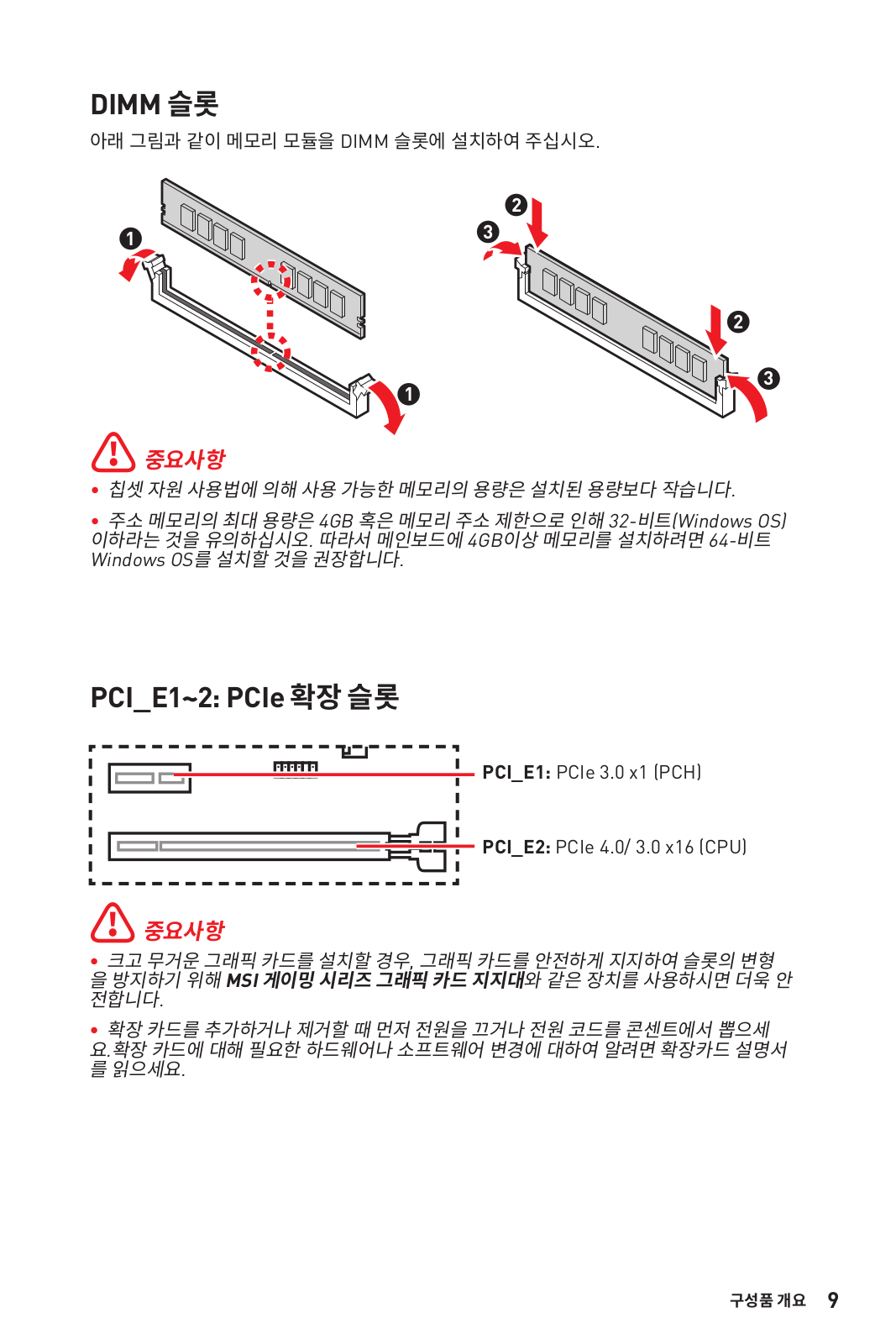

Loading…
+ 134 hidden pages
You need points to download manuals.
1 point = 1 manual.
You can buy points or you can get point for every manual you upload.
Buy points
Upload your manuals
View the manual for the MSI A520M-A Pro here, for free. This manual comes under the category motherboards and has been rated by 17 people with an average of a 9. This manual is available in the following languages: English. Do you have a question about the MSI A520M-A Pro or do you need help?
Ask your question here
MSI A520M-A Pro specifications
Below you will find the product specifications and the manual specifications of the MSI A520M-A Pro.
The msi a520m-a pro is a motherboard designed to support AMD processors using Socket AM4. It is compatible with various AMD Ryzen processors, including the 3rd generation Ryzen 3, 5, 7, and 9 models. This motherboard supports up to one SMP processor and features two DIMM memory slots that support both ECC and non-ECC memory types.
The motherboard supports a wide range of memory clock speeds, from 1866 to 4600 MHz. It can hold up to 64 GB of internal memory, and it also supports unbuffered memory. This motherboard is designed to support both HDD and SSD storage drives, with interfaces such as PCI Express 3.0 and SATA.
As for its physical attributes, the msi a520m-a pro is a standard form factor motherboard with dimensions of 22.6 centimeters by 18.3 centimeters. It uses high-quality materials and construction to ensure its reliability and durability over time.
Overall, the msi a520m-a pro is a reliable and efficient motherboard that provides solid performance for users looking to build a PC around it. Its broad compatibility, wide range of memory clock speeds, and support for various storage drives make it a flexible and useful option for those seeking to build a custom PC. Its small size and efficient design also make it a good choice for those looking to build smaller, more portable systems.
Processor manufacturer
AMD
Supported memory types
DDR4-SDRAM
Supported storage drive types
HDD & SSD
Parallel processing technology support
—
General
| Brand | MSI |
| Model | A520M-A Pro | A520M-A PRO |
| Product | motherboard |
| EAN | 0824142224007, 4719072749927 |
| Language | English |
| Filetype | User manual (PDF) |
Processor
| Processor manufacturer | AMD |
| Processor socket | Socket AM4 |
| Compatible processor series | AMD Ryzen 3 3rd Gen, AMD Ryzen 5 3rd Gen, AMD Ryzen 7 3rd Gen, AMD Ryzen 9 3rd Gen |
| Maximum number of SMP processors | 1 |
Memory
| Supported memory types | DDR4-SDRAM |
| Number of memory slots | 2 |
| Memory slots type | DIMM |
| Memory channels | Dual-channel |
| Supported memory clock speeds | 1866,2133,2400,2667,2800,2933,3000,3066,3200,3466,3600,3733,3866,4000,4133,4266,4400,4600 MHz |
| Maximum internal memory | 64 GB |
| Unbuffered memory | Yes |
Storage controllers
| Supported storage drive types | HDD & SSD |
| Supported storage drive interfaces | PCI Express 3.0, SATA |
| Number of HDDs supported | 5 |
| RAID levels | 0, 1,10 |
Graphics
| Parallel processing technology support | — |
| Maximum resolution | 4096 x 2160 pixels |
| Number of displays supported | 2 |
Internal I/O
| USB 2.0 connectors | 2 |
| USB 3.2 Gen 1 (3.1 Gen 1) connectors | 1 |
| USB 3.2 Gen 2 (3.1 Gen 2) connectors | 0 |
| Number of SATA III connectors | 4 |
| Number of SATA II connectors | 0 |
| Number of Parallel ATA connectors | 0 |
| Front panel audio connector | Yes |
| Front panel connector | Yes |
| ATX Power connector (24-pin) | Yes |
| CPU fan connector | Yes |
| Number of chassis fan connectors | 2 |
| Chassis intrusion connector | Yes |
Rear panel I/O ports
| USB 2.0 ports quantity | 2 |
| USB 3.2 Gen 1 (3.1 Gen 1) Type-A ports quantity | 4 |
| USB 3.2 Gen 1 (3.1 Gen 1) Type-C ports quantity | 0 |
| USB 3.2 Gen 2 (3.1 Gen 2) Type-A ports quantity | 0 |
| USB 3.2 Gen 2 (3.1 Gen 2) Type-C ports quantity | 0 |
| Ethernet LAN (RJ-45) ports | 1 |
| eSATA ports quantity | 0 |
| PS/2 ports quantity | 0 |
| Firewire (IEEE 1394) ports | 0 |
| VGA (D-Sub) ports quantity | 0 |
| HDMI ports quantity | 1 |
| DVI-D ports quantity | 1 |
| Headphone outputs | 1 |
| Microphone in | Yes |
Network
| Ethernet LAN | Yes |
| Ethernet interface type | Gigabit Ethernet |
| LAN controller | Realtek RTL8111H |
| Wi-Fi | No |
Features
| Component for | PC |
| Motherboard form factor | micro ATX |
| Motherboard chipset family | AMD |
| Audio chip | Realtek ALC892 |
| Audio output channels | 7.1 channels |
| Number of mounting holes | 8 |
| Motherboard chipset | AMD A520 |
Expansion slots
| PCI Express x1 (Gen 3.x) slots | 1 |
| PCI Express x16 (Gen 3.x) slots | 1 |
BIOS
Weight & dimensions
| Width | 236 mm |
| Depth | 200 mm |
| Height | 60 mm |
Logistics data
| Harmonized System (HS) code | 84733020 |
Other features
show more
Frequently Asked Questions
Can’t find the answer to your question in the manual? You may find the answer to your question in the FAQs about the MSI A520M-A Pro below.
How can I connect the front panel connectors to the motherboard?
To connect the front panel connectors, refer to the motherboard’s user manual for the exact pin layout. Usually, the connectors consist of power switch, reset switch, HDD LED, and power LED. Match these connectors with the corresponding pins on the motherboard, making sure the polarity is correct.
How do I properly install the MSI A520M-A Pro motherboard into my computer case?
To install the MSI A520M-A Pro motherboard, align it with the pre-installed standoffs in the case, making sure that the screw holes on the motherboard line up with the standoffs. Carefully lower the motherboard onto the standoffs and fix it in place using screws, taking care not to tighten them too much.
How do I install the Central Processing Unit onto the motherboard?
To install the CPU, lift the CPU socket lever on the motherboard and align the notches on the CPU with the corresponding alignment keys on the socket. Carefully place the CPU into the socket, making sure not to apply excessive pressure. Once correctly aligned, gently lower the lever to secure the CPU in place.
Where should I connect my storage devices, such as hard disk drives or solid-state drives?
The MSI A520M-A Pro motherboard usually offers multiple SATA ports for linking storage devices. Find these ports on the motherboard and utilize SATA cables to link your HDDs or SSDs, making sure to also connect power cables. It is vital to maintain proper cable management and organization inside the computer case.
What steps should I take to update the BIOS on my motherboard?
To update the BIOS, visit the MSI website and find the support page for the A520M-A Pro motherboard. Download the most recent BIOS update file that is specific to your motherboard model. Copy the file onto a USB flash drive. Restart your computer, and while it is starting up, press the designated key to enter the BIOS setup. Go to the BIOS update section and choose the file from your USB flash drive to start the update process. Follow the instructions that appear on the screen to finish the update.
Does the MSI A520M-A Pro support AMD Ryzen processors?
Yes, the MSI A520M-A Pro is compatible with AMD Ryzen 3rd Gen processors.
How many memory slots does the MSI A520M-A Pro have?
The MSI A520M-A Pro has 2 memory slots.
Can the MSI A520M-A Pro support ECC memory?
Yes, the MSI A520M-A Pro supports both ECC and non-ECC memory.
What are the supported memory clock speeds for the MSI A520M-A Pro?
The MSI A520M-A Pro supports a wide range of memory clock speeds, ranging from 1866 MHz to 4600 MHz.
How many hard disk drives can the MSI A520M-A Pro support?
The MSI A520M-A Pro can support up to 5 Hard Disk Drives (HDDs). Furthermore, it also supports various RAID levels such as 0, 1, and 10 for enhanced storage performance and data redundancy.
What is the weight of the MSI A520M-A Pro?
The MSI A520M-A Pro has a weight of 698 g.
What is the height of the MSI A520M-A Pro?
The MSI A520M-A Pro has a height of 60 mm.
What is the width of the MSI A520M-A Pro?
The MSI A520M-A Pro has a width of 236 mm.
What is the depth of the MSI A520M-A Pro?
The MSI A520M-A Pro has a depth of 200 mm.
Is the manual of the MSI A520M-A Pro available in English?
Yes, the manual of the MSI A520M-A Pro is available in English .
Is your question not listed? Ask your question here
1
Contents
Contents
2
3
6
LAN Port LED Status Table …………………………………………………………………………….6
7
CPU Socket …………………………………………………………………………………………………..8
DIMM Slots……………………………………………………………………………………………………9
PCI_E1~2: PCIe Expansion Slots ……………………………………………………………………..9
M2_1: M.2 Slot …………………………………………………………………………………………….10
SATA1~4: SATA 6Gb/s Connectors …………………………………………………………………10
JFP1, JFP2: Front Panel Connectors ……………………………………………………………..11
JAUD1: Front Audio Connector ……………………………………………………………………..11
ATX_PWR1, CPU_PWR1: Power Connectors …………………………………………………..12
JUSB1, JUSB2: USB 2.0 Connectors ………………………………………………………………13
JUSB3: USB 3.2 Gen1 Connector …………………………………………………………………..13
CPU_FAN1, SYS_FAN1: Fan Connectors ………………………………………………………..14
JTPM1: TPM Module Connector …………………………………………………………………….14
JCI1: Chassis Intrusion Connector …………………………………………………………………15
JCOM1: Serial Port Connector ………………………………………………………………………15
JBAT1: Clear CMOS (Reset BIOS) Jumper ………………………………………………………16
EZ Debug LED ……………………………………………………………………………………………..16
17
BIOS Setup ………………………………………………………………………………………………….18
Entering BIOS Setup …………………………………………………………………………………….18
Resetting BIOS …………………………………………………………………………………………….18
Updating BIOS……………………………………………………………………………………………..19
20
Installing Windows® 10 …………………………………………………………………………………20
Installing Drivers …………………………………………………………………………………………20
Installing Utilities ………………………………………………………………………………………..20
Thank you for purchasing the MSI®
motherboard. This User Guide gives information about
board layout, component overview, BIOS setup and software
installation.
Questo manuale d’istruzione è fornito da trovaprezzi.it. Scopri tutte le offerte per MSI B550M B550M-A Pro
- Manuals
- Brands
- MSI Manuals
- Motherboard
- A520M-A PRO
- Manual
-
Contents
-
Table of Contents
-
Bookmarks
User Manual of Product 1:
MSI A520M-A PRO Motherboard mATX — Supports AMD Ryzen
3rd Gen Processors, AM4, DDR4 Boost (4600MHz/OC), 1 x
PCIe 3.0 x1, 1 x M.2 Gen3 x4, Gigabit LAN
Need help?
Do you have a question about the A520M-A PRO and is the answer not in the manual?
Questions and answers
Subscribe to Our Youtube Channel
Related Manuals for MSI A520M-A PRO
Summary of Contents for MSI A520M-A PRO
-
Page 1
User Manual of Product 1: MSI A520M-A PRO Motherboard mATX — Supports AMD Ryzen 3rd Gen Processors, AM4, DDR4 Boost (4600MHz/OC), 1 x PCIe 3.0 x1, 1 x M.2 Gen3 x4, Gigabit LAN… -
Page 2: Table Of Contents
Thank you for purchasing the MSI® A320M-A PRO mother- board. This User Guide gives information about board layout, component overview, BIOS setup and software installation. Contents Safety Information ………………. 2 Specifications ………………..3 Package contents ……………….. 5 Rear I/O Panel ………………..6 LAN Port LED Status Table ………………6…
-
Page 3: Safety Information
Safety Information ∙ The components included in this package are prone to damage from electrostatic discharge (ESD). Please adhere to the following instructions to ensure successful computer assembly. ∙ Ensure that all components are securely connected. Loose connections may cause the computer to not recognize a component or fail to start.
-
Page 4: Specifications
Memory ∙ Supports non-ECC UDIMM memory ∙ Supports ECC UDIMM memory (non-ECC mode) * Please refer www.msi.com for more information on compatible memory. ∙ 1x PCIe 3.0 x16 slot ▪ Supports x16 speed with 1st, 2nd and 3rd Gen AMD Ryzen™…
-
Page 5
Continued from previous page AMD® A320 Chipset ∙ 6x USB 3.2 Gen1 (SuperSpeed USB) (4 Type-A ports on the back panel, 2 ports available through the internal connectors) ∙ 6x USB 2.0 (High-speed USB) ports (2 Type-A ports on the back panel, 4 ports available through the internal connectors) ∙… -
Page 6: Package Contents
COMMAND CENTER ∙ LIVE UPDATE 6 Software ∙ SMART TOOL ∙ X-BOOST CPU-Z MSI GAMING ∙ ∙ Google Chrome™, Google Toolbar, Google Drive ∙ Norton™ Internet Security Solution Package contents Please check the contents of your motherboard package. It should contain: ∙…
-
Page 7: Rear I/O Panel
Rear I/O Panel Line-in Line-out PS/2 Mouse USB 3.2 Gen1 PS/2 Keyboard DVI-D USB 2.0 Mic in LAN Port LED Status Table Link/ Activity LED Speed LED Status Description Status Description No link 10 Mbps connection Yellow Linked Green 100 Mbps connection Blinking Data activity Orange…
-
Page 8: Overview Of Components
Overview of Components DIMMA1 CPU Socket DIMMB1 CPU_PWR1 CPU_FAN1 SYS_FAN1 52.00mm* ATX_PWR1 SATA4 PCI_E1 SATA3 JBAT1 PCI_E2 JFP1 JFP2 JAUD1 SATA2 JTPM1 SATA1 JCI1 JCOM JUSB3 JUSB1 JUSB2 * Distance from the center of the CPU to the nearest DIMM slot. Overview of Components…
-
Page 9: Cpu Socket
Always unplug the power cord from the power outlet before installing or removing ∙ the CPU. Please retain the CPU protective cap after installing the processor. MSI will deal ∙ with Return Merchandise Authorization (RMA) requests if only the motherboard comes with the protective cap on the CPU socket.
-
Page 10: Dimm Slots
PCIe 2.0 x1 PCIe 2.0 x1 ⚠ Important If you install a large and heavy graphics card, you need to use a tool such as MSI ∙ Gaming Series Graphics Card Bolster to support its weight to prevent deformation of the slot.
-
Page 11: Jfp1, Jfp2: Front Panel Connectors
JFP1, JFP2: Front Panel Connectors These connectors connect to the switches and LEDs on the front panel. HDD LED + Power LED + HDD LED — Power LED — Reset Switch Power Switch Reset Switch Power Switch JFP1 Reserved No Pin HDD LED — HDD LED HDD LED +…
-
Page 12: Atx_Pwr1, Cpu_Pwr1: Power Connectors
ATX_PWR1, CPU_PWR1: Power Connectors These connectors allow you to connect an ATX power supply. +3.3V +3.3V +3.3V -12V Ground Ground PS-ON# Ground Ground Ground ATX_PWR1 Ground Ground PWR OK 5VSB +12V +12V +3.3V Ground Ground +12V CPU_PWR1 Ground +12V ⚠ Important Make sure that all the power cables are securely connected to a proper ATX power supply to ensure stable operation of the motherboard.
-
Page 13: Jusb1, Jusb2: Usb 2.0 Connectors
∙ damage. In order to recharge your iPad,iPhone and iPod through USB ports, please install ∙ MSI® SUPER CHARGER software. JUSB3: USB 3.2 Gen1 Connector These connectors allow you to connect USB 3.2 Gen1 ports on the front panel. Power USB2.0+…
-
Page 14: Jaud1: Front Audio Connector
JAUD1: Front Audio Connector This connector allow you to connect audio jacks on the front panel. MIC L Ground MIC R Head Phone R MIC Detection SENSE_SEND No Pin Head Phone L Head Phone Detection JCOM1: Serial Port Connector This connector allows you to connect the optional serial port with bracket. SOUT Ground No Pin…
-
Page 15: Jci1: Chassis Intrusion Connector
JCI1: Chassis Intrusion Connector This connector allows you to connect the chassis intrusion switch cable. Normal Trigger the chassis (default) intrusion event Using chassis intrusion detector Connect the JCI1 connector to the chassis intrusion switch/ sensor on the chassis. Close the chassis cover. Go to BIOS >…
-
Page 16: Bios Setup
BIOS Setup The default settings offer the optimal performance for system stability in normal conditions. You should always keep the default settings to avoid possible system damage or failure booting unless you are familiar with BIOS. ⚠ Important BIOS items are continuous update for better system performance. Therefore, the ∙…
-
Page 17: Resetting Bios
Updating BIOS Updating BIOS with M-FLASH Before updating: Please download the latest BIOS file that matches your motherboard model from MSI website. And then save the BIOS file into the USB flash drive. Updating BIOS: Insert the USB flash drive that contains the update file into the computer.
-
Page 18: Installing Os, Drivers & Utilities
Installing OS, Drivers & Utilities Please download and update the latest utilities and drivers at www.msi.com Installing Windows® 10 Power on the computer. Insert the Windows® 10 installation disc/USB into your computer. Press the Restart button on the computer case.
-
Page 19
Installing OS, Drivers & Utilities… -
Page 20
MSI® A320M-A PRO 메인보드를 구입해주셔서 감사합니다. 이 사용 설명서는 메인보드 레이아웃, 부품 개요, BIOS 설정 및 소프 트웨어 설치에 대한 상세 내역을 제공하고 있습니다. 목차 안전 지침 ………………….2 사양 ……………………3 제품 내용물………………….5 후면 I/O 패널 ………………… 6 LAN 포트… -
Page 21: 안전 지침
안전 지침 ∙ 이 패키지에 포함된 부품은 정전기 방전(ESD)에 의해 파손될 우려가 있으므로 다음의 설명에 따라 컴퓨터를 조립하기 바랍니다. ∙ 모든 부품이 제대로 연결되었는지 확인하세요. 제대로 연결되지 않을 경우, 컴퓨터가 부품을 인식하지 못하거나 컴퓨터를 켤 수가 없게 됩니다. ∙ 부품의 예리한 부분에 손을 다칠 수 있으므로 메인보드 취급시 가장자리 부분을 잡기 바랍니다.
-
Page 22
메모리 ∙ non-ECC UDIMM 메모리 지원 ∙ ECC UDIMM 메모리 (non-ECC 모드) 지원 * 호환 가능한 메모리에 대한 자세한 정보는 웹사이트 www.msi. com을 방문하여 알아보시기 바랍니다. ∙ PCIe 3.0 x16 슬롯 1개 ▪ 1,2세대 및 3세대 AMD Ryzen™ 프로세서로 x16 속도 지원… -
Page 23
이전 페이지로부터 계속 AMD® A320 칩셋 ∙ USB 3.2 Gen1 (슈퍼 스피드 USB) 6포트 (후면 패널에 A타입 4 포트, 내장 커넥터를 통해 2포트) ∙ USB 2.0 (하이 스피드 USB) 6포트 (후면 패널에 A타입 2포트, 내장 커넥터를 통해 4포트) ∙ Realtek® ALC892 코덱 오디오… -
Page 24: 제품 내용물
커맨드 센터 ∙ 라이브 업데이트 6 소프트웨어 ∙ 스마트 툴 ∙ X-부스트 CPU-Z MSI 게이밍 ∙ ∙ 구글 유틸리티 : 크롬, 툴바, 드라이브 ∙ 노턴™ 인터넷 시큐리티 솔루션 제품 내용물 메인보드 패키지의 내용물을 확인하십시오.다음 품목들이 패키지에 들어 있어야 합니다: ∙…
-
Page 25: 후면 I/O 패널
후면 I/O 패널 라인 입력 라인 출력 PS/2 마우스 USB 3.2 Gen1 PS/2 키보드 DVI-D USB 2.0 마이크 입력 LAN 포트 LED 상태 표시도 링크/ 통신 LED 속도 LED 상태 설명 상태 설명 LAN이 올바르게 10 Mbps 속도로 꺼짐 꺼짐 연결되지…
-
Page 26: 구성품 개요
구성품 개요 DIMMA1 CPU 소켓 DIMMB1 CPU_PWR1 CPU_FAN1 SYS_FAN1 52.00mm* ATX_PWR1 SATA4 PCI_E1 SATA3 JBAT1 PCI_E2 JFP1 JFP2 JAUD1 SATA2 JTPM1 SATA1 JCI1 JCOM JUSB3 JUSB1 JUSB2 * CPU 중심에서 가장 가까운 DIMM 슬롯까지의 거리 구성품 개요…
-
Page 27: Cpu 소켓
프로세서를 설치한 후, CPU 보호 캡을 보관하시기 바랍니다. 반품시 메인보드와 CPU 소켓 ∙ 보호 캡이 함께 제공되어야만 MSI에서 반품(RMA) 요청 처리를 진행할 수 있습니다CPU 설치 시, CPU 히트싱크를 반드시 설치하세요. CPU 히트싱크는 과열을 방지하고 시스템 성능을 유 지하는데 꼭 필요합니다.
-
Page 28: Dimm 슬롯
중요사항 ∙ 크고 무거운 그래픽 카드를 설치할 경우, 그래픽 카드를 안전하게 지지하여 슬롯의 변형을 방지하기 위해 MSI 그래픽 카드 지지대와 같은 장치를 사용하시면 더욱 안전합니다. 확장 카드를 추가하거나 제거할 때 먼저 전원을 끄거나 전원 코드를 콘센트에서 뽑으세 ∙ 요.확장 카드에 대해 필요한 하드웨어나 소프트웨어 변경에 대하여 알려면 확장카드 설명서…
-
Page 29: Jfp1, Jfp2: 전면 패널 커넥터
JFP1, JFP2: 전면 패널 커넥터 이 커넥터를 사용하여 전면 패널의 스위치 및 LED를 연결할 수 있습니다. HDD LED + Power LED + HDD LED — Power LED — Reset Switch Power Switch Reset Switch Power Switch JFP1 Reserved No Pin HDD LED — HDD LED HDD LED +…
-
Page 30: Atx_Pwr1, Cpu_Pwr1: 전원 커넥터
ATX_PWR1, CPU_PWR1: 전원 커넥터 이 커넥터를 사용하여 ATX 전원 공급 장치를 연결할 수 있습니다. +3.3V +3.3V +3.3V -12V Ground Ground PS-ON# Ground Ground Ground ATX_PWR1 Ground Ground PWR OK 5VSB +12V +12V +3.3V Ground Ground +12V CPU_PWR1 Ground +12V ⚠ 중요사항…
-
Page 31: Jusb1, Jusb2: Usb 2.0 커넥터
⚠ 중요사항 VCC 및 그라운드 핀을 정확히 연결하여야 손상을 방지할 수 있습니다. ∙ USB 포트를 통하여 iPad,iPhone 및 iPod를 충전하려면 MSI® SUPER CHARGER 유틸리 ∙ 티를 설치하시기 바랍니다. JUSB3: USB 3.2 Gen1 커넥터 이 커넥터를 사용하여 전면 패널의 USB 3.2 Gen1 포트를 연결할 수 있습니다.
-
Page 32: Jaud1: 전면 오디오 커넥터
JAUD1: 전면 오디오 커넥터 이 커넥터를 사용하여 전면 패널의 오디오 잭을 연결할 수 있습니다. MIC L Ground MIC R Head Phone R MIC Detection SENSE_SEND No Pin Head Phone L Head Phone Detection JCOM1: 시리얼 포트 커넥터 이 커넥터에 브래킷을 사용하여 옵션인 시리얼 포트를 연결할 수 있습니다. SOUT Ground No Pin…
-
Page 33: Jci1: 섀시 침입 커넥터
JCI1: 섀시 침입 커넥터 이 커넥터에 섀시 침입 스위치 케이블을 연결할 수 있습니다. 표준 상태 섀시 침입 이벤트 트리거 (기본 설정) 섀시 침입 탐지기 사용하기 JCI1 커넥터를 섀시의 섀시 침입 스위치/ 센서에 연결합니다. 섀시 커버를 닫습니다. BIOS > Security(보안) > Chassis Intrusion Configuration(섀시 침입 구성)으로 이동합니다.
-
Page 34: Bios(바이오스) 설정
BIOS(바이오스) 설정 기본 설정은 일반적인 조건에서 시스템의 안정성을 위해 최적의 성능을 제공합니다. BIOS에 익숙하지 않을 경우, 시스템 손상 또는 부팅 실패를 방지하기 위해 항상 기본 설정을 유지하기 바랍니다. ⚠ 중요사항 BIOS 항목은 시스템 성능 향상을 위해 지속적으로 업데이트됩니다. 따라서 여기에 제공된 ∙…
-
Page 35: Bios 리셋
BIOS를 재설정하려면 CMOS 클리어 점퍼 섹션을 참조하세요. BIOS(바이오스) 업데이트 M-FLASH로 BIOS 업데이트 업데이트 하기전 구입한 모듈에 맞는 최신 BIOS 파일을 MSI® 웹사이트에서 다운로드한 후 BIOS 파일을 USB 플래시 드라이브에 저장합니다. BIOS 업데이트: 업데이트 파일이 들어있는 USB 플래시 드라이브를 컴퓨터에 삽입합니다.
-
Page 36: Os, 드라이브 & 유틸리티 설치하기
OS, 드라이브 & 유틸리티 설치하기 공식 웹사이트 www.msi.com을 방문하여 최신 버전의 유틸리티와 드라이버를 다운로드 및 업데이트하세요. Windows® 10설치하기 컴퓨터의 전원을 켭니다. Windows® 10 설치 디스크/USB를 컴퓨터에 삽입합니다. 컴퓨터 케이스의 Restart 버튼을 누릅니다. 컴퓨터가 POST (Power-On Self Test)하는 동안 F11 키를 눌러 부팅 메뉴로 이동합니다.
-
Page 37
OS, 드라이브 & 유틸리티 설치하기… -
Page 38
Merci d’avoir acheté une carte mère MSI® A320M-A PRO. Ce manuel d’utilisateur fournit des informations sur le schéma, la vue d’ensemble des composants, la configuration du BIOS et l’installation des logiciels. Table des matières Informations de sécurité …………….. 2 Spécifications ………………..3 Contenu …………………. -
Page 39: Informations De Sécurité
Informations de sécurité ∙ Les composants dans l’emballage peuvent être endommagés par des décharges électrostatiques (ESD). Pour vous assurer de correctement monter votre ordinateur, veuillez vous référer aux instructions ci-dessous. ∙ Assurez-vous de bien connecter tous les composants. En cas de mauvaise connexion, il se peut que l’ordinateur ne reconnaisse pas le composant et que le démarrage échoue.
-
Page 40: Spécifications
Mémoire ∙ Support mémoire non-ECC UDIMM ∙ Support mémoire ECC UDIMM (mode non-ECC) * Veuillez vous référer au site www.msi.com pour plus d’informations sur la mémoire compatible. ∙ 1 x slot PCIe 3.0 x 16 ▪ Le mode x 16 est supporté par les processeurs AMD Ryzen™…
-
Page 41
Suite du tableau de la page précédente Chipset AMD® A320 ∙ 6 x ports USB 3.2 Gen1 (SuperSpeed USB) (4 ports Type-A sur le panneau arrière, 2 ports disponibles par l’intermédiaire des connecteurs internes) ∙ 6 x ports USB 2.0 (High-speed USB) (2 ports Type-A sur le panneau arrière, 4 ports disponibles par l’intermédiaire des connecteurs internes) ∙… -
Page 42: Contenu
COMMAND CENTER ∙ LIVE UPDATE 6 Logiciel ∙ SMART TOOL ∙ X-BOOST CPU-Z MSI GAMING ∙ ∙ Google Chrome™, Google Toolbar, Google Drive ∙ Norton™ Internet Security Solution Contenu Vérifiez tous les articles dans le carton d’emballage de votre carte mère.
-
Page 43: Panneau Arrière Entrée / Sortie
Panneau arrière Entrée / Sortie Entrée Ligne Sortie Ligne Souris PS/2 USB 3.2 Gen1 Clavier PS/2 DVI-D USB 2.0 Entrée Microphone Tableau explicatif de l’état de la LED du port LAN LED indiquant la LED indiquant la vitesse connexion et l’activité Etat Description Etat…
-
Page 44: Vue D’ensemble Des Composants
Vue d’ensemble des composants Socket processeur DIMMA1 DIMMB1 CPU_PWR1 CPU_FAN1 SYS_FAN1 52.00mm* ATX_PWR1 SATA4 PCI_E1 SATA3 JBAT1 PCI_E2 JFP1 JFP2 JAUD1 SATA2 JTPM1 SATA1 JCI1 JCOM JUSB3 JUSB1 JUSB2 * Distance entre le centre du CPU et le slot DIMM le plus proche. Vue d’ensemble des composants…
-
Page 45: Socket Processeur
Veuillez garder le capot de protection du processeur après l’installation du ∙ processeur. Selon les exigences de RMA (Return Merchandise Authorization), MSI n’acceptera pas les cartes mère dont le capot de protection aura été retiré. Lors de l’installation d’un processeur, n’oubliez pas d’installer un ventilateur pour ∙…
-
Page 46: Slots Dimm
Si vous installez une carte graphique lourde, il vous faut utiliser un outil comme ∙ la barre de support MSI Gaming Series pour supporter son poids et pour éviter la déformation du slot. Veillez à toujours mettre l’ordinateur hors tension et à débrancher le cordon d’al- ∙…
-
Page 47: Jfp1, Jfp2 : Connecteurs De Panneau Avant
JFP1, JFP2 : Connecteurs de panneau avant Ces connecteurs se lient aux interrupteurs et indicateurs LED du panneau avant. HDD LED + Power LED + HDD LED — Power LED — Reset Switch Power Switch Reset Switch Power Switch JFP1 Reserved No Pin HDD LED -…
-
Page 48: Atx_Pwr1, Cpu_Pwr1 : Connecteurs D’alimentation
ATX_PWR1, CPU_PWR1 : Connecteurs d’alimentation Ces connecteurs vous permettent de relier une alimentation ATX. +3.3V +3.3V +3.3V -12V Ground Ground PS-ON# Ground Ground Ground ATX_PWR1 Ground Ground PWR OK 5VSB +12V +12V +3.3V Ground Ground +12V CPU_PWR1 Ground +12V ⚠ Important Veuillez vous assurer que tous les câbles d’alimentation sont branchés aux connecteurs adéquats afin garantir une opération stable de la carte mère.
-
Page 49: Jusb1, Jusb2 : Connecteurs Usb 2.0
Pour recharger votre iPad, iPhone ou iPod par l’intermédiaire d’un port USB, ∙ veuillez installer le logiciel MSI® SUPER CHARGER. JUSB3 : Connecteur USB 3.2 Gen1 Ces connecteurs vous permettent de relier des ports USB 3.2 Gen1 sur le panneau avant.
-
Page 50: Jaud1 : Connecteur Audio Avant
JAUD1 : Connecteur audio avant Ce connecteur se lie aux jacks audio du panneau avant. MIC L Ground MIC R Head Phone R MIC Detection SENSE_SEND No Pin Head Phone L Head Phone Detection JCOM1 : Connecteur de port série Ce connecteur vous permet de relier un port série en option.
-
Page 51: Jci1 : Connecteur Intrusion Châssis
JCI1 : Connecteur intrusion châssis Ce connecteur est relié à un câble d’interrupteur intrusion châssis. Normal Commencer l’activité (défaut) intrusion châssis Utilisation du détecteur d’intrusion châssis Reliez le connecteur JCI1 à l’interrupteur ou au capteur d’intrusion châssis situé sur le boîtier du PC. Fermez le couvercle du boîtier.
-
Page 52: Configuration Du Bios
Configuration du BIOS Les réglages par défaut fournissent une performance optimale pour la stabilité du système en conditions normales. Veillez à toujours garder les réglages par défaut pour éviter d’endommager le système ou tout problème au démarrage, sauf si vous êtes familier avec le BIOS.
-
Page 53: Réinitialiser Le Bios
Avant la mise à jour : Veuillez télécharger la dernière version de BIOS compatible à votre carte mère sur le site MSI. Ensuite, veuillez sauvegarder le nouveau BIOS sur le lecteur flash USB. Mettre le BIOS à jour : Connectez le lecteur Flash USB contenant le profil à l’ordinateur.
-
Page 54: Installer Os, Pilotes & Utilitaires
Installer OS, Pilotes & Utilitaires Veuillez vous référer au site www.msi.com pour télécharger et mettre à jour les derniers utilitaires et pilotes Installer Windows® 10 Allumez l’ordinateur. Insérez le disque ou la clé USB d’installation de Windows® 10 dans votre ordinateur.
-
Page 55: Installer Les Utilitaires
Installer les utilitaires Avant d’installer les utilitaires, il faut compléter l’installation des pilotes. Ouvrez l’outil d’installation comme décrit ci-dessus. Cliquez sur l’onglet Utilities. Choisissez les utilitaires que vous voulez installer. Cliquez sur le bouton Install dans le coin inférieur droit de la fenêtre. L’installation des utilitaires commence.
-
Page 56
Danke, dass Sie sich für das MSI® A320M-A PRO Mother- board entschieden haben. Dieses Handbuch gibt informa- tionen über Motherboard-Layout, Komponentenübersicht, BIOS-Setup und Softwareinstallation. Inhalt Sicherheitshinweis ………………2 Spezifikationen ………………..3 Packungsinhalt ………………..5 Rückseite E/A ………………..6 LAN Port LED Zustandstabelle ………………6 Übersicht der Komponenten ……………. -
Page 57: Sicherheitshinweis
Sicherheitshinweis ∙ Die im Paket enthaltene Komponenten sind der Beschädigung durch elektrostatischen Entladung (ESD). Beachten Sie bitte die folgenden Hinweise, um die erfolgreichen Computermontage sicherzustellen. ∙ Stellen Sie sicher, dass alle Komponenten fest angeschlossen sind. Lockere Steckverbindungen können Probleme verursachen, zum Beispiel: Der Computer erkennt eine Komponente nicht oder startet nicht.
-
Page 58: Spezifikationen
Dual-Kanal-Speicherarchitektur Speicher Unterstützen non-ECC UDIMM-Speicher ∙ ∙ Unterstützen ECC UDIMM-Speicher (non-ECC Modus) * Weitere Informationen zu kompatiblen Speicher finden Sie unter: www.msi.com. ∙ 1x PCIe 3.0 x16 Steckplatz ▪ Unterstützt x16 Geschwindigkeit mit AMD Ryzen der 1., ™ 2. und 3. Generation Prozessoren ▪…
-
Page 59
Fortsetzung der vorherigen Seite AMD® A320 Chipsatz ∙ 6x USB 3.2 Gen1 (SuperSpeed USB) (4 Typ-A Anschlüsse an der rückseitigen Anschlussleiste, 2 Anschlüsse stehen durch die internen USB Anschlüsse zur Verfügung) ∙ 6x USB 2.0 (High-speed USB) ports (2 Typ-A Anschlüsse an der rückseitigen Anschlussleiste, 4 Anschlüsse stehen durch die internen USB Anschlüsse zur Verfügung) ∙… -
Page 60: Packungsinhalt
∙ COMMAND CENTER ∙ LIVE UPDATE 6 Software ∙ SMART TOOL ∙ X-BOOST ∙ CPU-Z MSI GAMING ∙ Google Chrome , Google Toolbar, Google Drive ™ ∙ Norton Internet Security Lösung ™ Packungsinhalt Überprüfen Sie den Packungsinhalt des Mainboards. Die Packung sollte enthalten: ∙…
-
Page 61: Rückseite E/A
Rückseite E/A Line-In Line-Out PS/2 Maus USB 3.2 Gen1 PS/2 Tastatur DVI-D USB 2.0 Mic In LAN Port LED Zustandstabelle Verbindung/ Aktivität LED Geschwindigkeit LED Zustand Bezeichnung Zustand Bezeichnung Keine Verbindung 10 Mbps-Verbindung Gelb Verbindung Grün 100 Mbps-Verbindung Blinkt Datenaktivität Orange 1 Gbps-Verbindung Audio 7.1-Kanal Konfiguration…
-
Page 62: Übersicht Der Komponenten
Übersicht der Komponenten DIMMA1 CPU Sockel DIMMB1 CPU_PWR1 CPU_FAN1 SYS_FAN1 52,00mm* ATX_PWR1 SATA4 PCI_E1 SATA3 JBAT1 PCI_E2 JFP1 JFP2 JAUD1 SATA2 JTPM1 SATA1 JCI1 JCOM JUSB3 JUSB1 JUSB2 * Abstand zwischen der Mitte der CPU und dem nächsten DIMM Steckplatz. Übersicht der Komponenten…
-
Page 63: Cpu Sockel
∙ Bitte bewahren Sie die CPU Schutzkappe nach der Installation des Prozessors auf. ∙ MSI wird RMA (Return Merchandise Authorization) Anfragen nur dann behandeln, wenn die Schutzklappe auf dem CPU-Sockel des Motherboards sitzt. ∙ Wenn Sie die CPU einbauen, denken sie bitte daran einen CPU-Kühler zu installie- ren.
-
Page 64: Dimm Steckplätze
DIMM Steckplätze Setzen Sie bitte ein Speichermodul wie untern gezeigt in den DIMM-Steckplatz ein. ⚠ Wichtig ∙ Aufgrund der Chipsatzressourcennutzung wird die verfügbare Kapazität des Spe- ichers kleiner sein als die Größe der installierten Speicherkapazität. Bitte beachten Sie, dass die maximale Kapazität eines 32-Bit-Windows-Be- ∙…
-
Page 65: Jfp1, Jfp2: Frontpanel-Anschlüsse
JFP1, JFP2: Frontpanel-Anschlüsse Diese Anschlüsse verbinden mit den Schaltern und LEDs auf des Frontpanels. HDD LED + Power LED + HDD LED — Power LED — Reset Switch Power Switch Reset Switch Power Switch JFP1 Reserved No Pin HDD LED — HDD LED HDD LED + POWER LED -…
-
Page 66: Atx_Pwr1, Cpu_Pwr1: Stromanschlüsse
ATX_PWR1, CPU_PWR1: Stromanschlüsse Mit diesen Anschlüssen verbinden Sie die ATX Stromstecker. +3.3V +3.3V +3.3V -12V Ground Ground PS-ON# Ground Ground Ground ATX_PWR1 Ground Ground PWR OK 5VSB +12V +12V +3.3V Ground Ground +12V CPU_PWR1 Ground +12V ⚠ Wichtig Stellen Sie sicher, dass alle Anschlüsse mit den richtigen Anschlüssen des Netzteils verbunden sind, um einen stabilen Betrieb der Hauptplatine sicherzustellen.
-
Page 67: Jusb1, Jusb2: Usb 2.0 Anschlüsse
Schäden kommen. Um das iPad, iPhone und den iPod über USB-Anschlüsse aufzuladen, installieren ∙ Sie bitte die MSI® SUPER CHARGER Software. JUSB3: USB 3.2 Gen1 Anschluss Mit diesem Anschluss können Sie den USB 3.2 Gen1 Anschluss auf dem Frontpanel verbinden.
-
Page 68: Jaud1: Audioanschluss Des Frontpanels
JAUD1: Audioanschluss des Frontpanels Dieser Anschluss ermöglicht den Anschluss von Audiobuchsen eines Frontpanels. MIC L Ground MIC R Head Phone R MIC Detection SENSE_SEND No Pin Head Phone L Head Phone Detection JCOM1: Serieller Anschluss Mit diesem Anschluss können Sie das optionale serielle Schnittstelle mit dem Einbausatze verbinden.
-
Page 69: Jci1: Gehäusekontaktanschluss
JCI1: Gehäusekontaktanschluss Dieser Anschluss wird mit einem Kontaktschalter verbunden. Normal Löse den Gehäuseeingriff (Standardwert) Gehäusekontakt-Detektor verwenden Schließen Sie den JCI1-Anschluss am Gehäusekontakt-Schalter/ Sensor am Gehäuse an. Schließen Sie die Gehäuseabdeckung. Gehen Sie zu BIOS > Security > Chassis Intrusion Configuration. Stellen Sie Chassis Intrusion auf Enabled.
-
Page 70: Bios-Setup
BIOS-Setup Die Standardeinstellungen bieten die optimale Leistung für die Systemstabilität unter Normalbedingungen. Sie sollten immer die Standardeinstellungen behalten, um mögliche Schäden des Systems oder Boot-Fehler zu vermeiden, außer Sie besitzen ausreichende BIOS Kenntnisse. ⚠ Wichtig ∙ BIOS Funktionen werden für eine bessere Systemleistung kontinuierlich aktualis- iert.
-
Page 71: Reset Des Bios
Aktualisierung des BIOS mit dem M-FLASH-Programm Vorbereitung: Laden Sie bitte die neueste BIOS Version, die dem Motherboard-Modell entspricht, von der offiziellen MSI Website herunter und speichern Sie die BIOS-Datei auf USB- Flash-Laufwerk. BIOS-Aktualisierungsschritte: Schließen das USB-Flashlaufwerk mit der BIOS-Datei an den Computer.
-
Page 72: Installation Von Os, Treibern Und Utilities
Installation von OS, Treibern und Utilities Laden Sie die neuesten Treiber und Dienstprogramme von www.msi.com herunter und aktualisieren Sie sie Installation von Windows® 10 Schalten Sie den Computer ein. Legen Sie die Windows® 10 Disk oder das USB-Flashlaufwerk in das optisches Laufwerk.
-
Page 73: Installation Von Utilities
Installation von Utilities Bevor Sie Anwendungen installieren, müssen Sie die Treiber-Installation vollständig beendet haben. Öffnen Sie den Installer wie beschrieben. Klicken Sie auf Utilities. Wählen Sie die Dienstprogramme, die installiert werden soll. Klicken Sie die Taste Install in der rechten unteren Ecke des Fensters. Die Utilities-Installation ist im Gange.
-
Page 74
Благодарим Вас за покупку материнской платы MSI® A320M-A PRO. Данное руководство пользователя содержит информацию о схеме платы, компонентах материнской платы и настройке BIOS и описании программного обеспечения. Содержание Безопасное использование продукции …………2 Технические характеристики …………… 3 Комплект поставки ………………5 Задняя… -
Page 75: Безопасное Использование Продукции
Безопасное использование продукции ∙ Компоненты, входящие в комплект поставки могут быть повреждены статическим электричеством. Для успешной сборки компьютера, пожалуйста, следуйте указаниям ниже. ∙ Убедитесь, что все компоненты компьютера подключены должным образом. Ослабленные соединения компонентов могут привести как к сбоям в работе, так и полной…
-
Page 76: Технические Характеристики
Память ∙ Поддержка non-ECC UDIMM памяти ∙ Поддержка ECC UDIMM памяти (в режиме non-ECC) * Пожалуйста, обратитесь www.msi.com для получения дополнительной информации о совместимой памяти. 1x слот PCIe 3.0 x16 ∙ ▪ Процессоры AMD Ryzen™ 1-го, 2-го и 3-го поколения…
-
Page 77
Продолжение с предыдущей страницы Контроллер AMD® A320 ∙ 6x портов USB 3.2 Gen1 (SuperSpeed USB) (4 порта Type-A на задней панели, 2 порта доступны через внутренние разъемы) ∙ 6x портов USB 2.0 (High-speed USB) (2 порта Type-A на задней панели, 4 порта доступны через внутренние разъемы) ∙… -
Page 78: Комплект Поставки
LIVE UPDATE 6 Программное ∙ SMART TOOL обеспечение ∙ X-BOOST ∙ CPU-Z MSI GAMING ∙ Google Chrome™, Google Toolbar, Google Drive ∙ Norton™ Internet Security Solution Комплект поставки Проверьте комплект поставки материнской платы. В него должны входить следующие элементы: ∙…
-
Page 79: Задняя Панель Портов Ввода/ Вывода
Задняя панель портов ввода/ вывода Линейный вход Линейный выход PS/2 мыши USB 3.2 Gen1 PS/2 клавиатуры DVI-D USB 2.0 Микрофонный вход Таблица состояний индикатора порта LAN Подключение/ Работа Скорость передачи данных индикатора Состояние Описание Состояние Описание Выкл. 10 Мбит/с подключение Выкл.
-
Page 80: Компоненты Материнской Платы
Компоненты материнской платы Процессорный DIMMA1 сокет DIMMB1 CPU_PWR1 CPU_FAN1 SYS_FAN1 52.00мм* ATX_PWR1 SATA4 PCI_E1 SATA3 JBAT1 PCI_E2 JFP1 JFP2 JAUD1 SATA2 JTPM1 SATA1 JCI1 JCOM JUSB3 JUSB1 JUSB2 * Расстояние от центра процессора до ближайшего слота DIMM. Компоненты материнской платы…
-
Page 81: Процессорный Сокет
питания. Пожалуйста, сохраните защитную крышку процессорного сокета после ∙ установки процессора. Любые возможные гарантийные случаи, связанные с работой материнской платы, MSI будет рассматривать только, при наличии защитной крышки на процессорном сокете. ∙ При установке процессора обязательно установите процессорный кулер. Кулер, представляющий собой систему охлаждения процессора, предупреждает…
-
Page 82: Слоты Dimm
⚠ Внимание! ∙ При установке массивной видеокарты, необходимо использовать такой инструмент, как MSI Gaming Series Graphics Card Bolster для поддержки веса графической карты и во избежание деформации слота. ∙ Перед установкой или извлечением плат расширения убедитесь, что кабель питания отключен от электрической сети. Прочтите документацию на карту…
-
Page 83: Jfp1, Jfp2: Разъемы Передней Панели
JFP1, JFP2: Разъемы передней панели Эти разъемы служат для подключения кнопок и светодиодных индикаторов, расположенных на передней панели. HDD LED + Power LED + HDD LED — Power LED — Reset Switch Power Switch Reset Switch Power Switch JFP1 Reserved No Pin HDD LED — HDD LED…
-
Page 84: Atx_Pwr1, Cpu_Pwr1: Разъемы Электропитания
ATX_PWR1, CPU_PWR1: Разъемы электропитания Данные разъемы предназначены для подключения коннекторов питания ATX. +3.3V +3.3V +3.3V -12V Ground Ground PS-ON# Ground Ground Ground ATX_PWR1 Ground Ground PWR OK 5VSB +12V +12V +3.3V Ground Ground +12V CPU_PWR1 Ground +12V ⚠ Внимание! Для обеспечения стабильной работы системной платы проверьте надежность подключения…
-
Page 85: Jusb1, Jusb2: Разъемы Usb 2.0
контакты VCC и земли. ∙ Для того, чтобы зарядить ваш iPad, iPhone и iPod через порты USB, пожалуйста, установите утилиту MSI® SUPER CHARGER. JUSB3: Разъем USB 3.2 Gen1 Данный разъем предназначен для подключения портов USB 3.1 Gen1 на передней панели.
-
Page 86: Jaud1: Разъем Аудио Передней Панели
JAUD1: Разъем аудио передней панели Данный разъем предназначен для подключения аудиоразъемов передней панели. MIC L Ground MIC R Head Phone R MIC Detection SENSE_SEND No Pin Head Phone L Head Phone Detection JCOM1: Разъем последовательного порта Данный разъем позволяет подключить последовательный порт, размещенный на внешнем…
-
Page 87: Jci1: Разъем Датчика Открытия Корпуса
JCI1: Разъем датчика открытия корпуса К этому разъему подключается кабель от датчика открытия корпуса. Нормально Разрешить запись по (По умолчанию) событию открытия корпуса Использование датчика открытия корпуса Подключите подключите датчик открытия корпуса к разъему JCI1. Закройте крышку корпуса. Войдите в BIOS > Security > Chassis Intrusion Configuration. Установите…
-
Page 88: Настройка Bios
Настройка BIOS Настройки по умолчанию обеспечивают оптимальную производительность и стабильность системы при нормальных условиях. Если вы недостаточно хорошо знакомы с BIOS, всегда устанавливайте настройки по умолчанию. Это позволит избежать возможных повреждений системы, а также проблем с загрузкой. ⚠ Внимание! ∙ С…
-
Page 89: Сборс Bios
к разделу джампер очистки данных CMOS. Обновление BIOS Обновление BIOS при помощи M-FLASH Подготовительные операции: Пожалуйста, скачайте последнюю версию файла BIOS с сайта MSI, который соответствует вашей модели материнской платы. Сохраните файл BIOS на флэш- диске USB. Обновление BIOS: Вставьте флэш-диск USB, содержащий файл обновления в компьютер.
-
Page 90: Установка Ос, Драйверов И Утилит
Установка ОС, драйверов и утилит Cкачайте и обновите последние утилиты и драйверы с сайта: www.msi.com. Установка Windows® 10 Включите компьютер. Вставьте диск Windows 10 в привод для оптических дисков или вставьте в ® разъем USB компьютера USB флэш-диск, содержащий установочный файл…
-
Page 91
Установка ОС, драйверов и утилит… -
Page 92
感谢您购买了 MSI® A320M-A PRO 主板。 本指南提供了主板布 局, 组件概述, BIOS 设置以及软件安装。 目录 安全信息………………….2 规格 ……………………3 包装内容………………….5 后置 I/O 面板 ………………..6 LAN 端口 LED 状态表 ………………..6 组件概述………………….7 CPU 底座 ……………………8 DIMM 插槽 ……………………9 PCI_E1~2: PCIe 扩展插槽 ……………….9 JFP1, JFP2: 前置面板接口… -
Page 93: 安全信息
安全信息 ∙ 此包装中包含的组件有可能受到静电放电 (ESD)损坏。 请遵守以下注意事项, 以确保 成功组装计算机。 ∙ 确保所有组件连接牢固。 若连接不紧可能会导致计算机无法识别组件或无法开启。 ∙ 拿起主板时请手持主板边缘, 避免触及主板的敏感组件。 ∙ 当拿取主板时, 建议佩戴静电放电 (ESD) 腕带, 以防止静电损坏其配置。 如果 ESD 腕带 无法使用, 请在拿取主板前通过接触其它金属物体释放自身的静电。 ∙ 在不安装主板时, 请将主板放在静电屏蔽容器或防静电垫上。 ∙ 在打开计算机前, 确保计算机机箱内的主板或任何位置上没有松动的螺丝或金属组 件。 ∙ 在安装完成之前不要启动计算机。 否则可能会导致组件永久性损坏以及伤害到使用 者。 ∙ 在任何安装步骤中, 如果您需要帮助, 请咨询专业的计算机技术员。 ∙ 安装或拆卸计算机任何组件之前,…
-
Page 94
双通道内存架构 内存 ∙ 支持 非-ECC UDIMM 内存 ∙ 支持 ECC UDIMM 内存 (非-ECC 模式) * 请参考 www.msi.com 网站, 以了解有关内存兼容的详细信息。 ∙ 1 个 PCIe 3.0 x16 插槽 ▪ 第一代, 第二代和第三 AMD 锐龙™ 处理器支持 x16 速率 ▪ 搭载 Radeon™ Vega Graphics 的锐龙™ 和搭载 Radeon™… -
Page 95
接上一页 AMD® A320 芯片组 ∙ 6 个 USB 3.2 Gen1 (SuperSpeed USB) (4 个 Type-A 后置面板 端口, 通过内部接口可使用 2 个端口) ∙ 6 个 USB 2.0 (High-speed USB) 端口 (2 个 Type-A 后置面板端 口, 通过内部接口可使用 4 个端口) ∙ Realtek® ALC892 解码芯片 音频… -
Page 96: 包装内容
∙ 驱动程序 ∙ 快速充电 ∙ COMMAND CENTER ∙ LIVE UPDATE 6 更新软件 软件 ∙ 智能工具 ∙ 一键加速技术 MSI GAMING 版 CPU-Z ∙ ∙ Google 浏览器 , Google 工具栏, Google 云端硬盘 ™ ∙ 诺顿™ 网络安全解决方案 包装内容 请检查您的主板包装内容。 它应包含以下内容: ∙ 主板 ∙…
-
Page 97: 后置 I/O 面板
后置 I/O 面板 音频输入 音频输出 PS/2 鼠标 USB 3.2 Gen1 麦克风输入 PS/2 键盘 DVI-D USB 2.0 LAN 端口 LED 状态表 连线/ 工作灯号 速度灯号 状态 描述 状态 描述 关 网络未连接 关 传输速率 10 Mbps 黄色 网络已连接 绿色 传输速率 100 Mbps 网络数据在使 橙色…
-
Page 98: 组件概述
组件概述 DIMMA1 CPU 底座 DIMMB1 CPU_PWR1 CPU_FAN1 SYS_FAN1 52.00毫米* ATX_PWR1 SATA4 PCI_E1 SATA3 JBAT1 PCI_E2 JFP1 JFP2 JAUD1 SATA2 JTPM1 SATA1 JCI1 JCOM JUSB3 JUSB1 JUSB2 * CPU 中心位置到最近的 DIMM 插槽的距离。 组件概述…
-
Page 99: Cpu 底座
CPU 底座 将 CPU 安装至 CPU 底座, 请如下图示。 ⚠ 注意 安装或移除 CPU 之前, 请先关闭电源, 并将电源线由插座上拔除。 ∙ 安装完成处理器后请保留 CPU 保护盖。 微星将要求授权的 (RMA) 在处理退货验证需 ∙ 要主板上附带 CPU 底座上的保护盖。 当您安装 CPU 时, 请确认已安装好 CPU 风扇。 对防止过热和维持系统的稳定性 CPU ∙ 风扇是非常必要的。 ∙ 确认在系统启动前 CPU 风扇已经牢固的粘贴在 CPU 上。 ∙…
-
Page 100: Dimm 插槽
的 Athlon™ 插槽 Athlon X4 PCI_E1 PCIe 3.0 x16 PCIe 3.0 x8 PCIe 3.0 x4 PCI_E2 PCIe 2.0 x1 PCIe 2.0 x1 PCIe 2.0 x1 ⚠ 注意 ∙ 如果您安装了一个大而重的显卡时, 您需要使用一个辅助工具如 MSI 游戏系列显卡支 架千斤顶来支撑其重量, 以防止插槽变形。 当添加或移除扩展卡时, 请先关闭电源, 并将电源线由插座上拔除。 请查看关于扩展卡 ∙ 的文档以便检查必要附件的硬件和软件变化。 组件概述…
-
Page 101: Jfp1, Jfp2: 前置面板接口
JFP1, JFP2: 前置面板接口 这些接口连接前置面板上的开关和 LED 灯。 HDD LED + Power LED + HDD LED — Power LED — Reset Switch Power Switch Reset Switch Power Switch JFP1 Reserved No Pin HDD LED — HDD LED HDD LED + POWER LED — POWER LED POWER LED + Speaker -…
-
Page 102: Atx_Pwr1, Cpu_Pwr1: 电源接口
ATX_PWR1, CPU_PWR1: 电源接口 这些接口允许您连接一个 ATX 电源供应器。 +3.3V +3.3V +3.3V -12V Ground Ground PS-ON# Ground Ground Ground ATX_PWR1 Ground Ground PWR OK 5VSB +12V +12V +3.3V Ground Ground +12V CPU_PWR1 Ground +12V ⚠ 注意 确认所有接口都已正确的连接到 ATX 电源供应器上, 以确保主板稳定的运行。 CPU_FAN1, SYS_FAN1: PWM 风扇接口 模式风扇接口使用速率控制信号提供恒定的…
-
Page 103: Jusb1, Jusb2: Usb 2.0 接口
USB0+ USB1+ Ground Ground No Pin ⚠ 注意 请注意, VCC 和 接地针脚必须正确连接以避免可能的损坏。 ∙ 为了将您的 iPad, iPhone 和 iPod 通过 USB 端口进行充电, 请安装 MSI SUPER ∙ ® CHARGER 实用程序。 JUSB3: USB 3.2 Gen1 接口 这些接口允许您连接前置面板上的 USB 3.2 Gen1 端口。 Power USB2.0+ USB3_RX_DN USB2.0-…
-
Page 104: Jaud1: 前置音频接口
JAUD1: 前置音频接口 此接口允许您连接前置面板上音频插孔。 MIC L Ground MIC R Head Phone R MIC Detection SENSE_SEND No Pin Head Phone L Head Phone Detection JCOM1: 串行端头接口 此接口允许您连接可选串行端口可用插槽。 SOUT Ground No Pin JTPM1: TPM 模组接口 此接口是用来连接 TPM (安全平台模组)。 请参考 TPM 安全平台手册以获得更多细节和 用法。 LPC Clock 3V Standby power LPC Reset 3.3V Power…
-
Page 105: Jci1: 机箱入侵检测接口
JCI1: 机箱入侵检测接口 此接口可用来连接机箱入侵检测开关线。 正常 启用机箱入侵检测 (默认) 使用机箱入侵检测器 JCI1 接口连接机箱上的机箱入侵检测开关/ 传感器。 合上机箱盖。 转到 BIOS > Security > Chassis Intrusion Configuration。 设置 Chassis Intrusion 为 Enabled。 按 F10 保存并退出, 然后按 Enter 键选择 Yes。 当计算机开启时, 一旦打开机箱盖, 将会在屏幕上显示一个警告信息。 重设机箱入侵警告 转到 BIOS > Security > Chassis Intrusion Configuration。 设置…
-
Page 106: Bios 设置
BIOS 设置 在正常情况下, 默认设置为系统稳定提供最佳性能。 您应该始终保持默认设置, 以避免可 能出现的系统损坏或无法开机, 除非您熟悉 BIOS 设置。 ⚠ 注意 为了获得更好的系统性能 , BIOS 项目描述不断更新 。 因此 , 这些描述可能有些稍微的 ∙ 不同 , 仅供参考 。 您也可以参考 BIOS 项目描述的帮助信息面板 。 本章中的图片仅供参考 , 可能与您所购买的产品而有差异 。 ∙ BIOS 项目将随处理器而变化。 ∙ 进入 BIOS 设置 在开机程序中,…
-
Page 107: 重启 Bios
注意 请参考清除 CMOS 跳线部分, 以了解重启 BIOS 的相关信息。 更新 BIOS 使用 M-FLASH 更新 BIOS 更新前 : 请从 MSI 的网站下载符合您主板型号的最新 BIOS 文件。 然后将 BIOS 文件保存到 U 盘中。 更新 BIOS : 插入内有欲更新文件的 U 盘到计算机上。 POST 过程中按 Del 键进入 BIOS 设置。 转至 BIOS > M-FLASH > Select one file to update BIOS, 选择一个 BIOS 文件执行…
-
Page 108: 安装操作系统, 驱动程序与工具程序
将 MSI 驱动光盘放入您光驱中。 ® 点击 Select to choose what happens with this disc 弹出式通知, 然后选择 Run DVDSetup.exe 来打开安装程序。 如果从 Windows 控制面板关闭 AutoPlay 功能, 您 仍然可以从 MSI 驱动程序光盘的根路径手动执行 DVDSetup.exe。 安装程序将在 Drivers/Software 选项卡中查找并列出所有必要的驱动程序。 点击窗口右下角的 Install 按钮。 驱动程序的安装将继续进行, 完成后将提示您重新启动。 点击 OK 按钮完成安装。 重新启动您的电脑。…
-
Page 109
安装操作系统 , 驱动程序与工具程序… -
Page 110
感謝您購買 MSI® A320M-A PRO 主機板 。 本用戶指南提供有關 電路板佈局 , 元件總覽 , BIOS 設置和軟體安裝的信息 。 目錄 安全說明………………….2 規格 ……………………3 包裝內容物 ………………….. 5 背板 I/O ………………….6 網路連接埠 LED 燈狀態表 ………………6 元件總覽………………….7 CPU 腳座 ……………………8 記憶體插槽 ……………………9 PCI_E1~2: PCIe 擴充插槽 ……………….9 JFP1, JFP2: 系統面板接頭… -
Page 111: 安全說明
安全說明 ∙ 本包裝內所含的組件可能因靜電 (ESD) 受到損壞 。 請務必依循以下指示 , 以確保能成 功組裝電腦 。 ∙ 請確定所有組件均確實連接妥善 。 如有鬆脫 , 可能會造成電腦無法識別該組件或無法 啟動電腦 。 ∙ 拿取主機板時 , 請抓主機板的邊緣 , 以免碰觸到較易損壞的組件 。 ∙ 拿取主機板時 , 建議您戴靜電手環 , 以免產生靜電損壞主機板 。 若無靜電手環 , 請先觸 摸其他金屬物品以讓自身放電 , 再碰觸主機板 。 ∙…
-
Page 112
雙通道記憶體架構 支援記憶體 ∙ 支援 non-ECC UDIMM 記憶體 ∙ 支援 ECC UDIMM 記憶體 (非-ECC 模式) * 有關兼容記憶體的更多資訊 , 請參閱 www.msi.com 。 ∙ 1 個 PCIe 3.0 x16 插槽 ▪ 第一、二、三代 AMD Ryzen™ 處理器支援 x16 速度 ▪ 搭載 Radeon™ Vega 顯示晶片的 Ryzen™ 處理器/ 搭… -
Page 113
承上頁 AMD® A320 晶片組 ∙ 6 個 USB 3.2 Gen1 (SuperSpeed USB) (4 個 Type-A 連接埠位 USB 連接埠 於背板上 , 2 個連接埠透過板載接頭提供) ∙ 6 個 USB 2.0 (High-speed USB) 連接埠 (2 個 Type-A 連接埠位 於背板上 , 4 個連接埠透過板載接頭提供) ∙ Realtek® ALC892 解碼晶片 音效… -
Page 114: 包裝內容物
SUPER CHARGER ∙ COMMAND CENTER ∙ LIVE UPDATE 6 軟體 ∙ SMART TOOL ∙ X-BOOST 效能強化技術 CPU-Z MSI GAMING ∙ ∙ Google Chrome™ 、 Google 工具列 、 Google 雲端硬碟 ∙ Norton™ Internet Security Solution 包裝內容物 請檢查您的主機板包裝的內容物 。 它應該包含 : ∙ 主機板…
-
Page 115: 背板 I/O
背板 I/O 音源輸入 音源輸出 網路連接埠 PS/2 滑鼠 USB 3.2 Gen1 PS/2 鍵盤 DVI-D USB 2.0 麥克風 輸入 網路連接埠 LED 燈狀態表 連線/ 工作燈號 速度燈號 狀態 說明 狀態 說明 關閉 未連線 關閉 傳輸速率 10 Mbps 黃燈 已連線 綠燈 傳輸速率 100 Mbps 閃爍 資料傳輸中…
-
Page 116: 元件總覽
元件總覽 DIMMA1 CPU 腳座 DIMMB1 CPU_PWR1 CPU_FAN1 SYS_FAN1 52.00mm* ATX_PWR1 SATA4 PCI_E1 SATA3 JBAT1 PCI_E2 JFP1 JFP2 JAUD1 SATA2 JTPM1 SATA1 JCI1 JCOM JUSB3 JUSB1 JUSB2 * 從 CPU 中心到最近的 DIMM 插槽之間的距離 。 元件總覽…
-
Page 117: Cpu 腳座
CPU 腳座 請將 CPU 安裝到 CPU 插槽中 , 如下所示 。 ⚠ 重要 請務必先將電源線由電源插座移除 , 再安裝或取下中央處理器 。 ∙ CPU 安裝後 , 仍請將 CPU 腳座的保護蓋留存 。 日後若需送修主機板 , 腳座上必須裝有 ∙ 保護蓋 , 才符合微星的 Return Merchandise Authorization (RMA) 要求 , 以保固維修主 機板 。 ∙…
-
Page 118: 記憶體插槽
PCIe 3.0 x8 PCIe 3.0 x4 PCI_E2 PCIe 2.0 x1 PCIe 2.0 x1 PCIe 2.0 x1 ⚠ 重要 若安裝大型顯卡 , 需要使用工具如 MSI Gaming Series 顯卡支撐架 , 以支撐其重量和 ∙ 防止插槽變形 。 ∙ 新增或移除擴充卡時 , 請確認已關機並拔除電源線 。 請詳讀擴充卡說明文件 , 檢查使用 擴充卡所需變更的軟硬體設定 。 元件總覽…
-
Page 119: Jfp1, Jfp2: 系統面板接頭
JFP1, JFP2: 系統面板接頭 這些接頭用於連接前面板的開關和 LED 指示燈 。 HDD LED + Power LED + HDD LED — Power LED — Reset Switch Power Switch Reset Switch Power Switch JFP1 Reserved No Pin HDD LED — HDD LED HDD LED + POWER LED — POWER LED POWER LED + Speaker -…
-
Page 120: Atx_Pwr1, Cpu_Pwr1: 電源接頭
ATX_PWR1, CPU_PWR1: 電源接頭 這些接頭能讓您連接 ATX 電源供應器 。 +3.3V +3.3V +3.3V -12V Ground Ground PS-ON# Ground Ground Ground ATX_PWR1 Ground Ground PWR OK 5VSB +12V +12V +3.3V Ground Ground +12V CPU_PWR1 Ground +12V ⚠ 重要 請確認所有電源排線 , 皆已穩固連接到適當的 ATX 電源供應器 , 確保主機板穩定操作 。 CPU_FAN1, SYS_FAN1: PWM 風扇電源接頭…
-
Page 121: Jusb1, Jusb2: Usb 2.0 接頭
No Pin ⚠ 重要 請注意 , VCC 和接地針腳必須正確連接 , 以免造成組件受損 。 ∙ 如要以 USB 連接埠對 iPad 、 iPhone 及 iPod 充電 , 請安裝 MSI® SUPER CHARGER 工 ∙ 具軟體 。 JUSB3: USB 3.2 Gen1 接頭 這些接頭用於連接前面板的 USB 3.2 Gen1 連接埠 。…
-
Page 122: Jtpm1: Tpm 模組接頭
JAUD1:前置音效插孔 本插孔用於連接前面板的音訊插孔 。 MIC L Ground MIC R Head Phone R MIC Detection SENSE_SEND No Pin Head Phone L Head Phone Detection JCOM1: 序列埠接頭 此接頭用來連接選擇性配置的序列埠托架 。 SOUT Ground No Pin JTPM1: TPM 模組接頭 此接頭用於連接可信賴平台模組 (TPM) 。 請參閱 TPM 安全平台手冊瞭解更多詳情 。 LPC Clock 3V Standby power LPC Reset…
-
Page 123: Jci1: 機殼開啟接頭
JCI1: 機殼開啟接頭 此接頭可連接機殼開啟開關排線 一般 觸動機殼開啟事件 (預設值) 使用機殼開啟偵測器 連接 JCI1 插孔和機殼上的機殼開啟開關/感測器 。 關閉機殼蓋 。 前往 BIOS > Security > Chassis Intrusion Configuration 。 將 Chassis Intrusion 設定為 Enabled 。 按下 F10 儲存並離開 , 然後按 Enter 鍵選擇 Yes 。 若機殼蓋再次開啟 , 電腦啟動後畫面上會出現警告訊息 。 重設機殼開啟警告…
-
Page 124: Bios 設定
BIOS 設定 預設值提供最佳效能 , 可在一般情況下達到系統穩定度 。 除非您熟悉 BIOS 設定 , 否則請 務必使用預設值 , 以免系統受損或開機失敗 。 ⚠ 重要 BIOS 項目會持續更新達到更優異的系統效能 。 因此 , 說明內容可能會與最新的 BIOS ∙ 稍微不同 , 因此僅供參考 。 您亦可參閱 HELP 取得 BIOS 項目說明 。 本節的圖片僅供參考 , 可能與您所購買的產品有所不同 。 ∙ BIOS 項目將隨處理器而變化…
-
Page 125: 重設 Bios
請參閱清除 CMOS 跳線以重置 BIOS 。 更新 BIOS 以 M-FLASH 更新 BIOS 更新前 : 請從 MSI 網站下載符合您主機板型號的最新 BIOS 檔案 。 然後將 BIOS 檔案存到 USB 隨身碟 。 更新 BIOS : 將內含更新檔的 USB 隨身碟插入電腦 。 在 POST 期間按下 Del 鍵 , 進入 BIOS 設定畫面 。…
-
Page 126: 安裝操作系統、驅動程式和公用程式
安裝驅動程式 啟動電腦進入 Windows 10 。 ® 將 MSI 驅動程式光碟放到光碟機 。 ® 點擊 選擇要針對此光碟執行的動作 的彈出通知,然後選擇 執行 DVDSetup.exe 以打開安裝程式。 如果從 Windows 設定面板關閉自動播放功能,仍然可以從 MSI 驅動程式光碟的根路徑手動執行 DVDSetup.exe。 安裝程式將在 驅動程式 / 應用軟體 頁面中搜索並列出所有必要的驅動程式。 點擊窗口右下角的 安裝 按鈕。 接著會開始進行驅動程式安裝,完成之後會要求您重新啟動電腦。 按一下 確定 按鈕完成。 重新啟動電腦。 安裝公用程式 安裝公用程式前 , 務必完成驅動程式安裝 。…
-
Page 127
安裝操作系統 、 驅動程式和公用程式… -
Page 128
この度はMSI® A320M-A PROマザーボードをお買い上げいただ き、 誠にありがとうございます。 このユーザーガイドはボードレイ アウ ト、 コンポーネン トの概要、 およびBIOSの設定についての情 報を掲載しています。 目次 安全に関する注意事項 ………………2 仕様 ……………………3 パッケージの内容 ………………… 5 リアI/Oパネル ………………..6 LANポートLED状態表 ………………..6 コンポーネントの概要 ………………7 CPUソケッ ト …………………….8 DIMMスロッ ト ………………….9 PCI_E1~2: PCIe拡張スロッ ト ………………9 JFP1、… -
Page 129: 安全に関する注意事項
安全に関する注意事項 ∙ 本パッケージ内のコンポーネン トは静電放電(ESD)を受けやすいので、 PCの組み立てを 確実に成功させるために以下の注意事項を守って ください。 ∙ コンポーネン トがしっかりと全部接続され手いることを確認して ください。 確実に接続さ れていない場合、 コンポーネン トの認識不良や起動不良の原因となります。 ∙ 繊細な部品に触れないよう、 マザーボードのフチを持って ください。 ∙ マザーボードを扱う際には、 静電気破壊を防ぐために、 静電放電 (ESD)リストストラップ を着けることをお薦めします。 ESDリストストラップが用意できない場合は、 他の金属製の ものに触れて静電気を逃してからマザーボードを扱って ください。 ∙ 本品を取り付けない時は、 静電気対策が施された箱か、 または静電気防止パッ ド上で 保管して ください。 ∙ コンピューターの電源を投入する前に、 マザーボードのショートの原因となる、 外れたネ ジや金属製の部品がマザーボード上またはPCケース内にないか、…
-
Page 130
1866/ 2133/ 2400/ 2667(OC)/ 2933(OC)/ 3200(OC)+ MHz をサポート ∙ デュアルチャンネルメモリアーキテクチャ メモリ ∙ Non-ECC UDIMMメモリをサポート ∙ ECC UDIMMメモリをサポート (non-ECCモード) * 互換性があるメモリの詳細については、 www.msi.comからご 参照ください。 ∙ PCIe 3.0 x16スロッ ト x1 ▪ AMD Ryzen™第1/2/3世代プロセッサは x16をサポート Radeon Vegaグラフィ ックス付きのAMD® Ryzen™プロセッ ▪ サ/Radeon™グラフィ ックス付きの第2世代AMD Ryzen™プロ… -
Page 131
前のページから続く ∙ Realtek® ALC892コーデック オーディオ ∙ 7.1チャンネルHDオーディオ Realtek 8111H Gigabit LANコン トローラー x1 ∙ PS/2キーボードポート x1 ∙ PS/2マウスポート x1 ∙ DVI-Dポート x1 ∙ HDMI™ポート x1 バックパネルコ ネクター ∙ USB 3.2 Gen1 Type-Aポート x4 LAN (RJ45)ポート x1 ∙ ∙ USB 2.0 Type-Aポート x2 ∙… -
Page 132: パッケージの内容
デバイスドライバー ∙ SUPER CHARGER ∙ COMMAND CENTER ∙ LIVE UPDATE 6 ソフトウェア ∙ SMART TOOL ∙ X-BOOST CPU-Z MSI GAMING ∙ ∙ Google Chrome™, Google Toolbar, Google Drive ∙ Norton™ Internet Security Solution パッケージの内容 パッケージにすべての添付品が含まれていることをご確認ください。 ∙ マザーボード本体 ∙ ドライバーDVD ∙…
-
Page 133: リアI/Oパネル
リアI/Oパネル ライン入力 ライン出力 PS/2マウス USB 3.2 Gen1 PS/2キーボード DVI-D USB 2.0 マイク入力 LANポートLED状態表 リンク/ アクティビティLED スピードLED 状態 解説 状態 通信速度 リンクしていません 10 Mbps 黄色 リンクしています 緑色 100 Mbps 点滅 データ通信中です オレンジ 1 Gbps 7.1チャンネルオーディオの設定 7.1チャンネルオーディオを設定するには、フロントオーディオI/Oモジュールを JAUD1コネクターに接続してから、下記の手順に従ってください。 Realtek HD Audio Manager > Advanced Settingsをクリ ックし 、 以下のダイアログ を開きます。…
-
Page 134: コンポーネントの概要
コンポーネントの概要 DIMMA1 CPUソケッ ト DIMMB1 CPU_PWR1 CPU_FAN1 SYS_FAN1 52.00mm* ATX_PWR1 SATA4 PCI_E1 SATA3 JBAT1 PCI_E2 JFP1 JFP2 JAUD1 SATA2 JTPM1 SATA1 JCI1 JCOM JUSB3 JUSB1 JUSB2 * CPUの中央から最近のDIMMスロッ トまでの直線距離。 コンポーネントの概要…
-
Page 135: Cpuソケット
CPUソケット 下図のようにCPUをCPUソケッ トに取り付けて ください。 ⚠ 注意 CPUの脱着は、 必ず電源をオフにし、 コンセン トから電源ケーブルを抜いてから行って ∙ ください。 CPUを取り付けた後、 CPUソケッ トに取り付けられていたCPUソケッ トカバーは絶対に ∙ 捨てないでください。 本製品の修理を依頼される際に、 CPUソケッ トカバーがCPUソケッ ト に取り付けられていない場合は修理をお断りすることがございます。 CPUを取り付ける際は、 必ずCPUクーラーも取り付けて ください。 CPUクーラーは過熱 ∙ を防ぎ、 システムの安定を保つために必要です。 ∙ システムを起動する前に、 CPUクーラーがCPUとしっかりと密着していることを確認し て ください。 CPUの過熱はCPU自身やマザーボードに深刻なダメージを与えるおそれがあります。 シ ∙ ステム組み立て後初回起動時に必ずCPUファンが正常に動作していることを確認して くだ さい。…
-
Page 136: Dimmスロット
PCIe 3.0 x4 PCI_E2 PCIe 2.0 x1 PCIe 2.0 x1 PCIe 2.0 x1 ⚠ 注意 張カードの着脱は、 必ず電源をオフにし、 コンセン トから電源ケーブルを抜いてから行っ ∙ て ください。 ハードウェアまたはソフ トウェアにどのような変更が必要であるかは、 拡張カ ードのドキュメン トでご確認ください。 大型且つ重いグラフィ ックスカードをインストールすると、 スロッ トの変形を防止するた ∙ めに、 MSI Gaming Series Graphics Card Bolsterのようなツールを使用することが必要 です。 リアI/Oパネル…
-
Page 137: Jfp1、 Jfp2: フロントパネルコネクター
JFP1、 JFP2: フロントパネルコネクター これらのコネクターにはフロン トパネルのスイッチとLEDを接続します。 HDD LED + Power LED + HDD LED — Power LED — Reset Switch Power Switch Reset Switch Power Switch JFP1 Reserved No Pin HDD LED — HDD LED HDD LED + POWER LED — POWER LED POWER LED + Speaker -…
-
Page 138: Atx_Pwr1、 Cpu_Pwr1: 電源コネクター
ATX_PWR1、 CPU_PWR1: 電源コネクター これらのコネクターにはATX電源を接続します。 +3.3V +3.3V +3.3V -12V Ground Ground PS-ON# Ground Ground Ground ATX_PWR1 Ground Ground PWR OK 5VSB +12V +12V +3.3V Ground Ground +12V CPU_PWR1 Ground +12V ⚠ 注意 マザーボードの安定した動作を確実にするために、 全ての電源ケーブルが適切なATX電源 ユニッ トにしっかりと接続されていることを確認して下さい。 CPU_FAN1、 SYS_FAN1: PWMファンコネクター PWMモードファンコネクターには常時12Vが出力されており、 スピードコン トロール信号に よ…
-
Page 139: Jusb1、 Jusb2: Usb 2.0コネクター
USB1- USB0+ USB1+ Ground Ground No Pin ⚠ 注意 VCCピンとグランドピンは必ず接続して ください。 正し く接続されていない場合、 機器が ∙ 損傷するおそれがあります。 これらのUSBポートでiPad、 iPhoneとiPodを再充電するには 、 MSI® SUPER CHARGER ∙ ユーティ リティをインストールして ください。 JUSB3: USB 3.2 Gen1コネクター このコネクターにはフロン トパネルのUSB 3.2 Gen1ポートを接続します。 Power USB2.0+ USB3_RX_DN USB2.0- USB3_RX_DP Ground…
-
Page 140: Jaud1: フロントオーディオコネクター
JAUD1: フロントオーディオコネクター このコネクターにはフロン トパネルのオーディオジャ ックを接続します。 MIC L Ground MIC R Head Phone R MIC Detection SENSE_SEND No Pin Head Phone L Head Phone Detection JCOM1: シリアルポートコネクター このコネクターにはオプションのブラケッ ト付きのシリアルポートを接続します。 SOUT Ground No Pin JTPM1: TPMモジュールコネクター このコネクターはTPM (Trusted Platform Module)を接続します。 詳細についてはTPMセ キュリティ プラッ トホームマニュアルを参照して下さい。 LPC Clock 3V Standby power LPC Reset…
-
Page 141: Jci1: ケース開放スイッチコネクター
JCI1: ケース開放スイッチコネクター このコネクターにはケース開放スイッチケーブルを接続します。 正常 ケース開放イベン ト トリ (デフ ォルト) ガー有効 ケース開放検知機能の使い方 JCI1コネクターをケース開放スイッチ/センサーに接続します。 ケースのカバーを閉じます。 BIOS > Security > Chassis Intrusion Configurationに入ります。 Chassis IntrusionをEnabledに設定します。 F10を押すと、 設定を保存して終了するかメッセージが出ますので、 Enterキーを押し てYesを選択します。 ケースが開けられるとシステムに開放の情報が記録され、 次回のシステム起動時に警 告メッセージが表示されます。 ケース開放警告のリセット BIOS > Security > Chassis Intrusion Configurationに入ります。 Chassis IntrusionをResetに設定します。 F10を押すと、 設定を保存して終了するかメッセージが出ますので、 Enterキーを押し てYesを選択します。…
-
Page 142: Biosの設定
BIOSの設定 BIOSのデフ ォルト設定は、 通常の使用においてシステムの安定性のために最適な性能を 提供します。 ユーザーがBIOSに精通していない場合は、 起こり得るシステムへのダメージ や起動の失敗を防ぐために、 常にデフ ォルト設定のままにすべきです。 ⚠ 注意 BIOSは性能の向上のために、 継続的に変更と修正が行われています。 最新のBIOSと本 ∙ 書の内容に齟齬が発生してしまう場合があります 。 あらかじめご承知おき ください。 BIOS の設定項目の詳細はHELP情報パネルを参照して ください。 本章の図はあくまでも一例です。 お買い上げの製品と異なる場合がありますので、 ご承 ∙ 知おき ください。 ∙ BIOSの項目はプロセッサにより異なる場合があります。 BIOSセットアップ画面の起動 起動中に、 「 Press DEL key to enter Setup Menu, F11 to enter Boot Menu」 というメッセ ージが表示されている間に、…
-
Page 143: Biosのリセット
一つ選択し、 BIOSアップデートのプロセスを開始させます。 アップデートプロセスが完了した後、 システムが自動的に再起動します。 MSI DRAGON CENTERでのBIOSアップデート アップデートの前に: LANドライバーがインス トールされ、 インターネッ ト接続が正し く設定されていることを確 認して ください。 BIOSのアップデート: MSI LIVE UPDATE 6 をインストールして起動させます。 BIOS アップデートを選択します。 「スキャン」 ボタンをクリックします。 「ダウンロード」アイコンをクリックし、最新のBIOSファイルをダウンロード してインストールします。 Next をクリックして In Windows mode を選択します。それから、Next と Start を クリックして BIOS のアップデートを始めます。 アップデートプロセスが完了した後、システムが自動的に再起動します。…
-
Page 144: Os 、 ドライバーおよびユーティ リティのインストール
OS、 ドライバー及びユーティリティのインス トール www.msi.comから最新のユーティ リティと ドライバーをダウンロードしてアップデートし ます。 Windows® 10のインストール PCの電源をオンにします。 Windows® 10のインス トールメディア/USBを光学ドライブに挿入します。 PCケースのRestartボタンを押します。 POST (Power-On Self Test)中にF11キーを押し、 ブートメニューに入ります。 ブートメニューから光学ドライブを選択します。 Press any key to boot from CD or DVD… というメッセージが表示されたら、 任意の キーを押します。 (スペースキーやEnterキーが無難です。 ) 画面に表示される説明に従ってWindows® 10をインストールします。 ドライバーのインストール Windows® 10を起動させます。 MSI®ドライバーディ スクを光学ドライブに挿入します。…
-
Page 145
OS 、 ドライバー及びユーティリティのインストール… -
Page 146
EU REACH Regulation Compliance with these directives is assessed (Regulation EC No. 1907/2006 of the European using applicable European Harmonized Parliament and the Council), MSI provides Standards. the information of chemical substances in The point of contact for regulatory matters… -
Page 147
окружающей среды использованным proizvoda kojima je istekao vek trajanja, koji электрическим и электронным imaju MSI oznaku i koji su prodati u EU. Ove оборудованием (директива WEEE 2002/96/ proizvode možete vratiti na lokalnim mestima EC), вступающей в силу 13 августа 2005 года, za prikupljanje. -
Page 148
EK irányelve szerint az elektromos és Kể từ ngày 01/12/2012, tất cả các sản phẩm elektronikus berendezések többé nem do công ty MSI sản xuất tuân thủ Thông tư số kezelhetőek lakossági hulladékként, és az ilyen 30/2011/TT-BCT quy định tạm thời về giới hạn elektronikus berendezések gyártói kötelessé… -
Page 149
Alternatively, please try the ∙ Visit the MSI website and locate a nearby following help resources for further guidance. distributor for further recycling information. ∙ Visit the MSI website for technical guide, Users may also reach us at gpcontdev@msi.